Other Parts Discussed in Thread: ALP
E2E members,
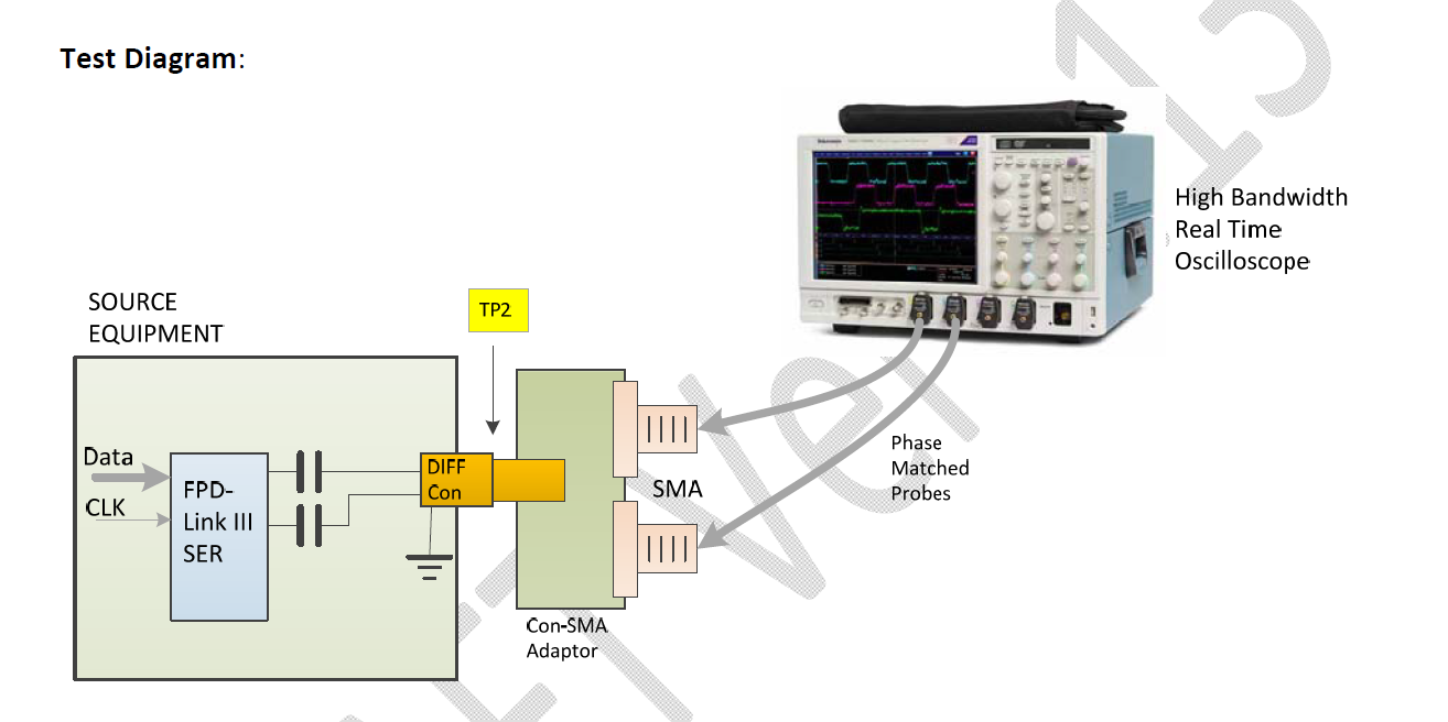
I would like to measure the waveform of FPD-Link III output that like datasheet "9.2.3.1 Application Performance Plots".
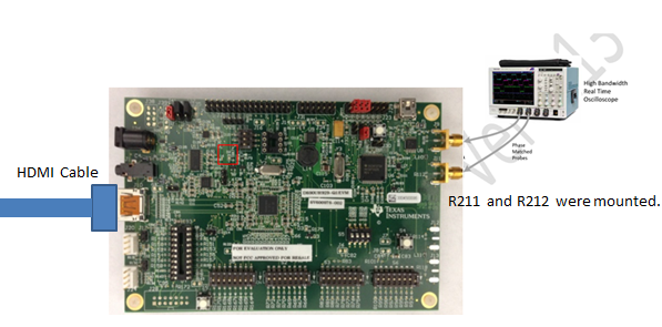
1. Can I get it on DS90UH929-Q1EVM?
2. Could you tell me how to measure waveform of FPD-Link III output on EMV?
- measurement points
- how to set register for measurement
Regards,
Nao