This thread has been locked.

If you have a related question, please click the "Ask a related question" button in the top right corner. The newly created question will be automatically linked to this question.

TMDS181: Strange behaviour with register 0x0B

Part Number: TMDS181

Hi,

We are using the TMDS181 in Sink application with video @4K60Hz.

We have seen that when we give the input with standard hardware strappings with below settings:

I2C Enabled, Sig_En high, PRE_Sel No connection, EQ_sel high, TX_Term_ctl low

We see that in one of the boards it works fine for both @4K60Hz & @4K30Hz; In other boards only @4K30Hz is working fine and @4K60 is not coming up.

So we moved into I2C control section and we found that in working board the value of 0x0B register @4K30Hz is 0xD8 and @4K60Hz its 0xDA dynamically updated as the input changes

But in the non working boards we see that it's always 0xD8 and not updating according to the input.

when we change manually (register 0x0B with 0xDA) we see that it's working fine @4K60Hz.

What could be causing the issue in the non working board, as the settings are same on all the boards & also the input is same.

Anyone please help.

Thanks & Regards,

Nanjunda M

  • Nanjunda

    As part of discovery, the source reads the sink’s E-EDID information to understand the capabilities of the sink. Part of this read is HDMI Forum Vendor Specific Data Block (HF-VSDB) MAX_TMDS_Character_Rate byte to determine the data rate supported. Depending upon the value, the source writes to slave address 0xA8 offset 0x20 bit1, TMDS_CLOCK_RATIO_STATUS. The TMDS181 snoops this write to determine the TMDS clock ratio and thus sets its own TMDS_CLOCK_RATIO_STATUS bit accordingly. If a 1 is written, then the TMDS clock is set to 1/40th of TMDS bit period. If a 0 is written, then the TMDS clock is set to 1/10th of TMDS bit period. The TMDS181 defaults to 1/10th of TMDS bit period unless a 1 is written to address 0xA8 offset 0x20 bit 1. When HPD is deasserted, this bit is reset to default values. If the source does not write this bit, the TMDS181 will not be configured for TMDS clock 1/40th mode in support of HDMI2.0a.

    The register you read shows the TMDS_CLOCK_RATIO_STATUS bit is not toggling between 4K 30Hz and 4K 60Hz, how are you connecting the DDC bus and what are the pullup resistors value on the DDC_SDA and DDC_SCL?

    Thanks
    David
  • Hi David,

    Thanks for the reply.

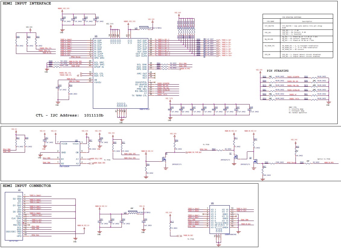
    We have given the pull-ups as per the Figure 35 of datasheet. i.e. 47K for each line from redriver to Connector and 2K ohm each between redriver and our FPGA.

    Below is the schematics for your reference.

    Please Note that the issue we are observing in few boards and few boards are working fine.


    Could you please let us know why we may be getting this issue?

    Thanks & Regards,

    Nanjunda M

  • Nanjunda

    Please take a look at this e2e post: e2e.ti.com/.../626622. Can you verify if you see similar behavior?

    Thanks
    David
  • Hi David,

    I think it's a little bit different situation,
    We have a working board with same design and non working board with same design and settings on the board for TMDS181.

    We have the input and output clock same at the TMDS181 in both working and non-working boards at all the resolutions(4k60 or 30). We have not checked toggling the HPD when there is no output.

    How could this be resolved if we do not get any difference from toggling of the HPD ?

    Thanks & Regards,
    Nanjunda M
  • Nanjunda

    Please check the toggling of HPD, other option is to toggle the apply_rxtx_change or the pd_en bit.

    Thanks
    David
  • Hi David,

    We tried to remove and reconnecting the input to TMDS181 and we are not seeing any input change with 4K60 and we see the same setting as before in the non working board.

    Thanks & Regards,

    Nanjunda M

  • Nanjunda

    For a sink side application, HPD needs consideration. The TMDS181 drives the HPD signal to 3.3 V, which meets requirements, but if 5 V HPD signaling is required, the two circuits shown in Figure 35 are required. As sources are not consistent in implementing all aspects of the DDC link, TI recommends to configure the TMDS181 as per Figure 35. Another consideration for how HPD is implemented is the architecture and behavior
    of the HDMI RX/scalar. The standard requires sinks to clear the TMDS_CLOCK_RATIO_STATUS in the SCDC when either +5 V power signal from source is not present or when hot plug detect pin goes low for 100 ms or more. When HPD goes low, the TMDS181 automatically clears this bit. The TMDS181 expects the TMDS_CLOCK_RATIO_STATUS bit to be set with a write from source to receiver/sink. If this does not happen,
    the TMDS181 may come up in the wrong configuration.

    So you have two possible sources of why 0x0Bh register is not being updated. One is HPD not toggling, the other is the write from source to sink is not successful on DDC lines.

    On the HPD, please check to see if it is toggling, and if it is going low, please make sure it goes low for 100ms or more.

    On the DDC, for the sink side application, you only need 47k pullup, not the 2k pullup. On the FPGA, do you have a way to tell if the write is successful?

    Thanks
    David