This thread has been locked.

If you have a related question, please click the "Ask a related question" button in the top right corner. The newly created question will be automatically linked to this question.

XIO3130: Interface between XIO3130 and External EEPROM.

Part Number: XIO3130
Other Parts Discussed in Thread: XIO2001, , SN74AHC1GU04

Hello,

In our Design, We are using  two XIO3130 PCIE Switch and connected the UP Stream Port to P1020’s SerDes1 & SerDes2 Port.

One EEPROM (AT24C04D-XHM-T) is connected with Each XIO3130 Switch through I2C.

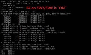
When we keep the SCL pin of I2C Low (SW3/SW4 -Pin#4 ON), we can see the all PCIE Switch in u-Boot but after keeping the SCL High(SW3/SW4 -Pin#4 OFF) the u-Boot can’t detect the PCIE Switch.

Here EEPROM is pre-programmed Externally as per TI Forum’s Guidance using Ardino.

We also share the Images for the u-Boot and EEPROM file for reference.

Regards,

Alpesh

4331.2821.XIO3130_V2.txt
4C	01000111
00	00000000
24	00100100
00	00000000
00	00000000
00	00000000
00	00000000
00	00000000
00	00000000
00	00000000
00	00000000
00	00000000
00	00000000
00	00000000
00	00000000
00	00000000
00	00000000
00	00000000
00	00000000
00	00000000
01	00000001
00	00000000
00	00000000
00	00000000
00	00000000
14	00010100
32	00110010
02	00000010
00	00000000
00	00000000
00	00000000
00	00000000
00	00000000
00	00000000
00	00000000
00	00000000
00	00000000
24	00100100
3F	00111111
04	00000100
01	00000001
00	00000000
01	00000001
00	00000000
00	00000000
00	00000000
00	00000000
14	00010100
32	00110010
10	00010000
60	01100000
1A	00011010
00	00000000
00	00000000
02	00000010
00	00000000
01	00000001
00	00000000
00	00000000
00	00000000
00	00000000
14	00010100
32	00110010
10	00010000
60	01100000
1A	00011010
00	00000000
00	00000000
02	00000010
00	00000000
01	00000001
00	00000000
00	00000000
00	00000000
00	00000000
14	00010100
32	00110010
10	00010000
60	01100000
1A	00011010
00	00000000
00	00000000

  • Alpesh,

    To make sure I understand your issue, you are experiencing that the XIO3130 is not detectable after a hard reset and SCL is pulled high? Are you experiencing this on all your platforms/ devices? or only some of them? If you replace the current XIO3130 with a new XIO3130, is the issue still seen? Could you probe the SCL and SDA line to see what is happening during your test? Could you ensure that you power rails to XIO3130 are clean and the power up sequence in section 3.1.1 is followed?
  • Malik,

    Thank you very much.

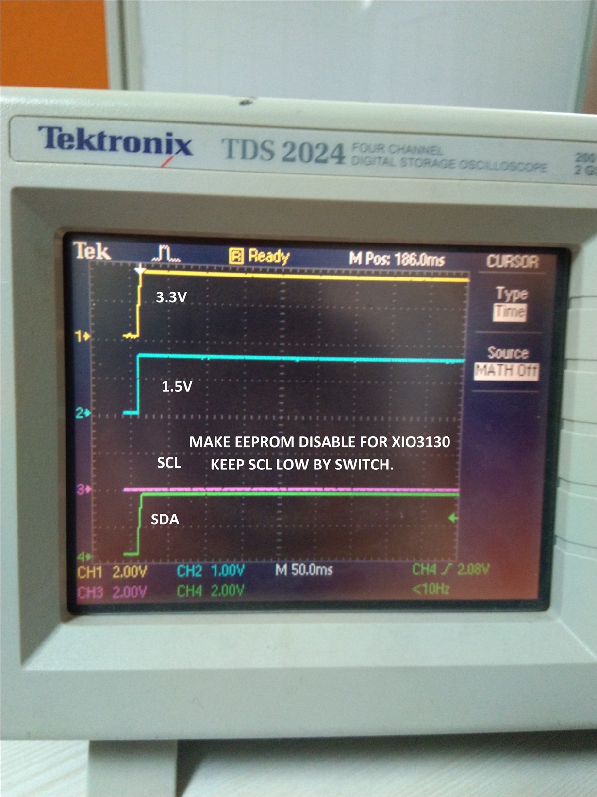
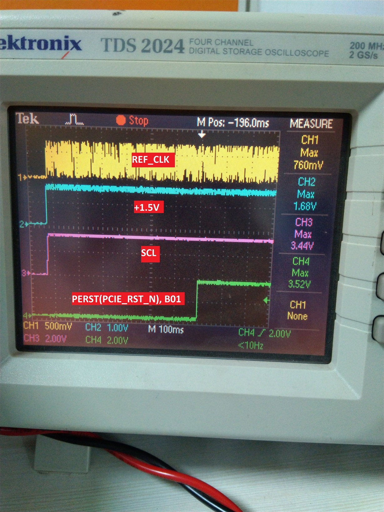
    Actually we can access the XIO3130 switch when we keep EEPROM Disable by making SCL LOW and that time Log display the PCIE Switch in u-boot but when we keep the EEPROM Enable by making SCL High and Log display the PCIE Switch is not Detect. Images are already sent in last post. 

    We observe the same problem in all Assembled Proto-Boards (5 Qty).

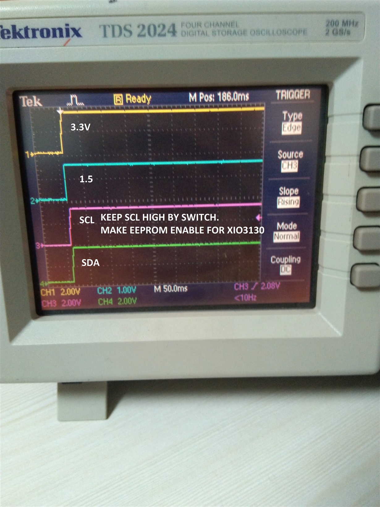
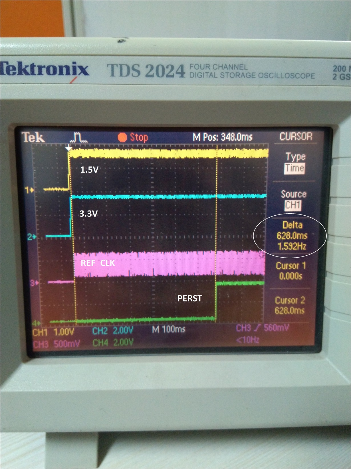
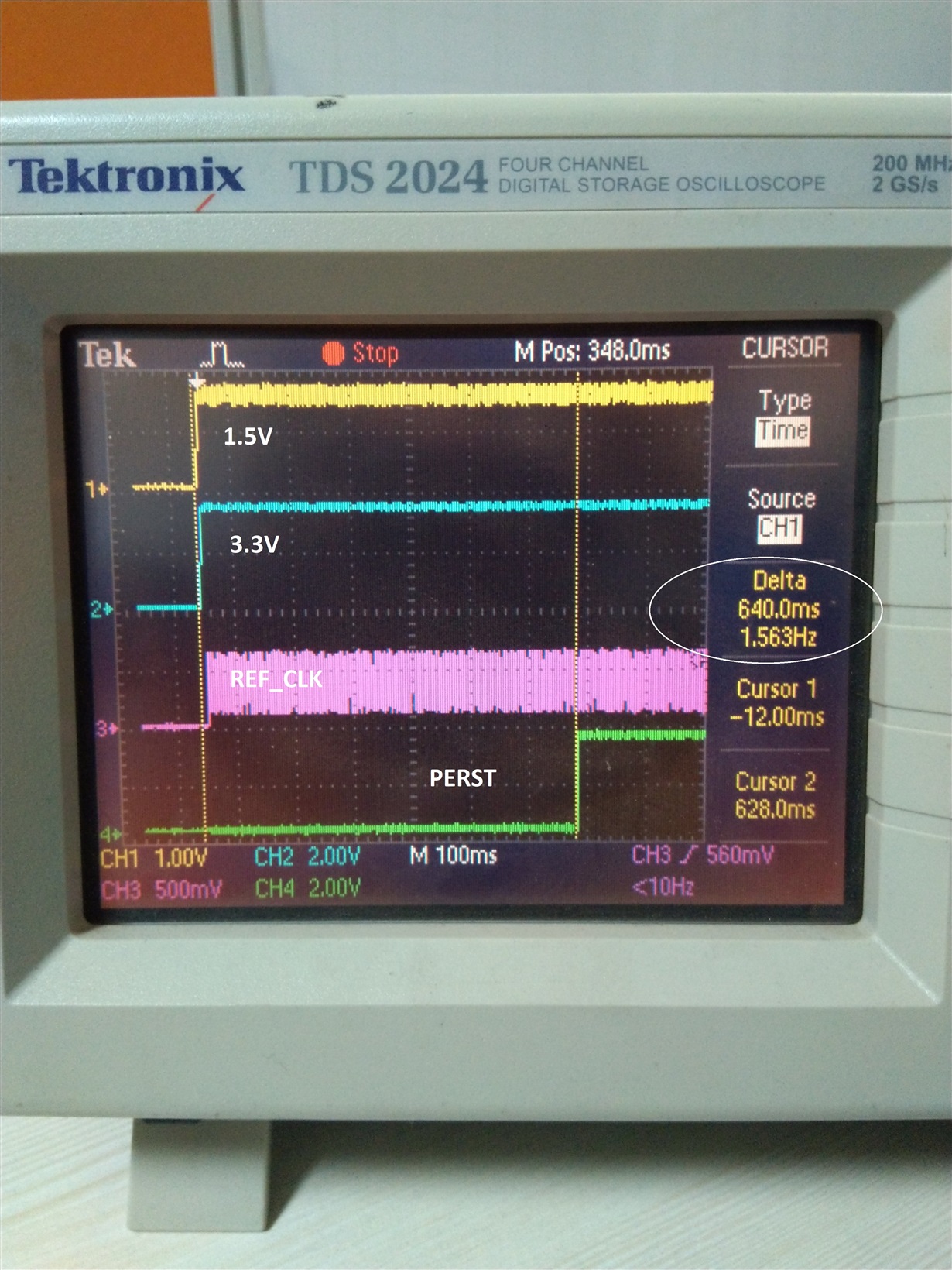
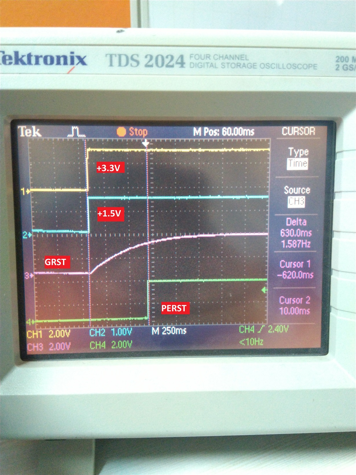
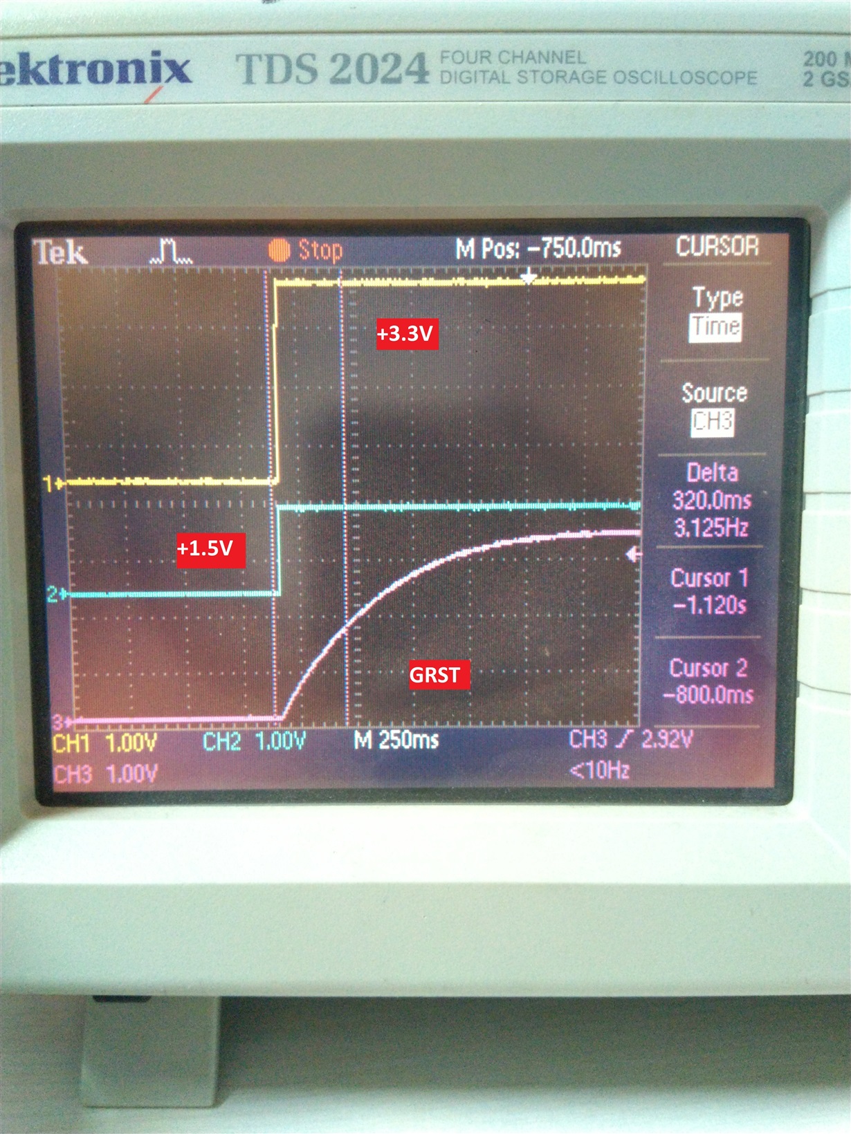
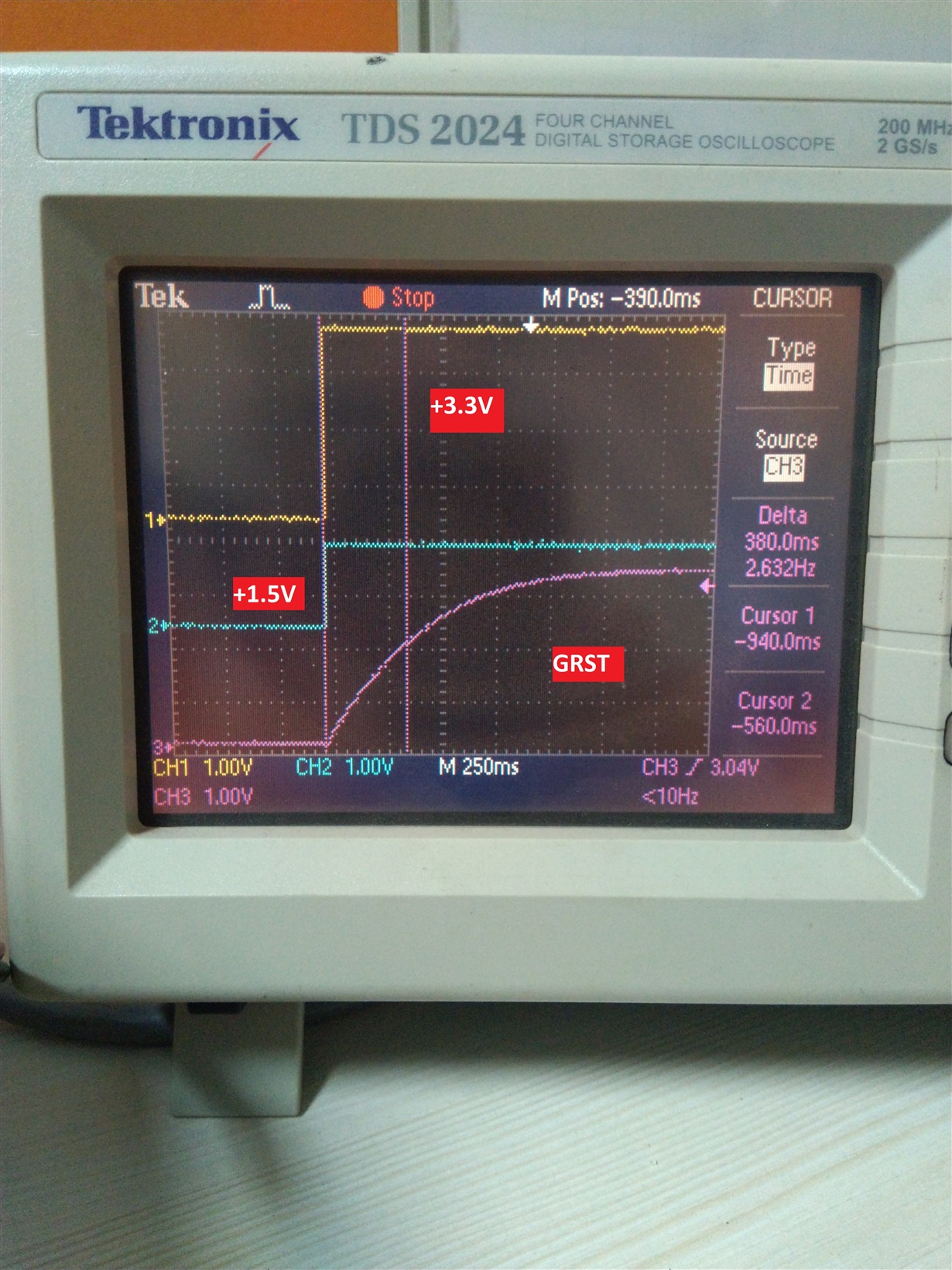
    I have attached the Images for the I2C and Power Up sequences in our Board as per your suggestion.

    Regards,

    Alpesh.

    Image-1: I2C_EEPROM_ENABLE.jpg

    Image-2: I2C_EEPROM_DISABLE.jpg

    Image-3: CLK TO RST_TIMING.jpg

    Image-4: VDD TO RST_TIMING.jpg

  • alpesh,

    Is there a PCB schematic that I could review for this application? Also I highly recommend a swap test in this case. Is GRST being asserted when power is stable?

  • Malik,

    Please provide your Professional Mail ID so I can share the Schematic. We will discuss the Schematic over there.

    I have no idea about the swap Test. Can you please guide me for that?

    We fix 4.7K  Pull up Resistor at GRST pin.

    Regards,

  • Hi Alpesh,

    I have sent you a private message in regard to the schematic.

    To perform a swap test:

    1. Put a non functional unit on one of your known functional boards to see if it still fails
    2. Take a good/new unit off of an  known functional board and put it on one of the newer failing boards to see if it passes or fails.

    This will help to determine whether or not it's an issue with the unit itself.

    What voltage is GRST pulled up to? We normally recommend to tie GRST to a "power good" signal for the 3.3 V or 1.5 V rails. (whichever comes up last)

  • Hi Malik,

    I have shared the schematic through E2E private message.

    Actually we have 7 Proto Board and all have same issue so I cannot perform the Swap Test.

    GRST is held Pull up with 3.3V now So shecked the voltage generated sequence and found that the +1.5V is generated Last then change the Pull Up from +3.3V to +1.5V but there is no change in result.

    Regards,

    Alpesh.

  • Alpesh,

    I have received your schematic and will get my notes to you (if any) by Friday afternoon.

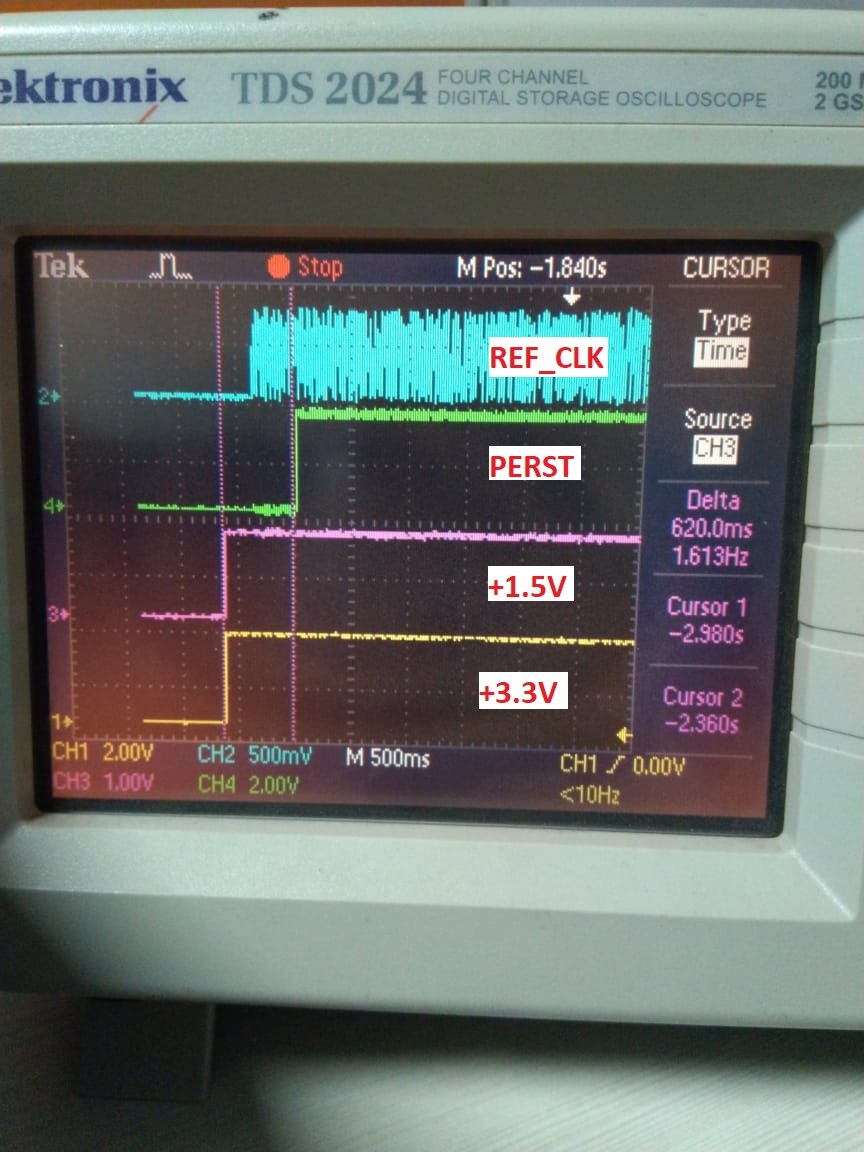
    Could you show SCL, PERST, REFCLK and 1.5 V on the same scope capture? Please include when PERST is de-asserted and 200 ms after this event.

  • Hi Malik,

    Thank you very much.

    Please find the attached Image as per your suggestion.

    Regards,

    Alpesh.

  • Hi Alpesh,

    I could not find any errors on my first pass through your schematic.

    My current suspicion is that XIO3130 is not coming out of reset correctly. This most likely has to do with the timing of GRST. Is it possible for you to monitor the current consumption of XIO3130 during your testing? If so, please measure I_1.5 or I_3.3 (current consumption from 1.5 V and 3.3 V rails respectively) to make sure they are at nominal values specified in 6.8 POWER CONSUMPTION of the data manual. Could you also try increasing the the delay between GRST and when power becomes stable? Try values greater than 10ms. See if this affects the current consumption of the device or your ability to read the EEPROM/Detect the XIO3130.
  • Hi Malik,

    Thank you very much for the Review.

    1. Actually +1.5V and +3.3V are connected to Power Plane. So, we cannot measure the individual Current but we have measured the Total Input Power and Current which is mentioned below:
      1.     +24V@340mA is the constant current for the Design.
    2. We had Try to Increase the Delay in GRST by Hardware (RC), there is already 4.7K Pullup on GRST so we add the 100uF Capacitor from GRST to GND. I have attached the Images for the results.
    3. We had make two iteration 
      1.    When EEPROM is Enable - attached the Log file "XIO3130_08022019_EEPROM_ENABLE.log".
      2.    When EEPROM is Disable - attached the Log file "XIO3130_08022019_EEPROM_DISABLE.log

    Our Observation:-

    • EEPROM  is different in EVM and Current Design (EVM -128X8 with 4 Slot and Our Design 512X8 with 1 Slot). So, is there any communication difference for that?

    Please check the attachments and provide your Inputs.

    Regards,

    Alpesh.

    XIO3130_08022019_EEPROM_DISABLE.log
    
    
    U-Boot 2014.07QorIQ-SDK-V1.7+g659b6a2 (Jan 03 2019 - 00:32:07)
    
    CPU0:  P1020E, Version: 1.1, (0x80ec0011)
    Core:  e500, Version: 5.1, (0x80212051)
    Clock Configuration:
           CPU0:800  MHz, CPU1:800  MHz, 
           CCB:400  MHz,
           DDR:200  MHz (400 MT/s data rate), LBC:25   MHz
    L1:    D-cache 32 KiB enabled
           I-cache 32 KiB enabled
    Board: P1020WLAN CPLD: V5.0 PCBA: V4.0
    rom_loc: nor upper bank
    SD/MMC : 4-bit Mode
    eSPI : Enabled
    I2C:   ready
    SPI:   ready
    DRAM:  Configuring DDR for 400 MT/s data rate
    1 GiB (DDR3, 16-bit, CL=4.5, ECC off)
    Flash: 64 MiB
    L2:    256 KiB enabled
    NAND:  256 MiB
    EEPROM: Invalid ID (ff ff ff ff)
    PCIe1: Root Complex of mini PCIe SLOT, x1 gen1, regs @ 0xffe0a000
      01:00.0     - 104c:8232 - Bridge device
       02:00.0    - 104c:8233 - Bridge device
       02:01.0    - 104c:8233 - Bridge device
       02:02.0    - 104c:8233 - Bridge device
    PCIe1: Bus 00 - 05
    [initial_xio3103]-0 Read Register [0xB3]=0x00 
    [initial_xio3103]-0 update Register [0xB3] to 0x08 
    [initial_xio3103]-0 Read Register again [0xB3]=0x00 
    PCIe2: Root Complex of PCIe SLOT, x1 gen1, regs @ 0xffe09000
      07:00.0     - 104c:8232 - Bridge device
       08:00.0    - 104c:8233 - Bridge device
       08:01.0    - 104c:8233 - Bridge device
       08:02.0    - 104c:8233 - Bridge device
    PCIe2: Bus 06 - 0b
    [initial_xio3103]-1 Read Register [0xB3]=0x00 
    [initial_xio3103]-1 update Register [0xB3] to 0x08 
    [initial_xio3103]-1 Read Register again [0xB3]=0x00 
    In:    serial
    Out:   serial
    Err:   serial
    Net:   eTSEC1 [PRIME], eTSEC3, enc0.0
    Hit any key to stop autoboot: 10  9  8  7  6  5  4  3  2  1  0 
    Unknown command 'usb' - try 'help'
    Unknown command 'ext2load' - try 'help'
    Unknown command 'ext2load' - try 'help'
    WARNING: adjusting available memory to 30000000
    Wrong Image Format for bootm command
    ERROR: can't get kernel image!
    => 
    XIO3130_08022019_EEPROM_ENABLE.log
     8 
    
    U-Boot 2014.07QorIQ-SDK-V1.7+g659b6a2 (Jan 03 2019 - 00:32:07)
    
    CPU0:  P1020E, Version: 1.1, (0x80ec0011)
    Core:  e500, Version: 5.1, (0x80212051)
    Clock Configuration:
           CPU0:800  MHz, CPU1:800  MHz, 
           CCB:400  MHz,
           DDR:200  MHz (400 MT/s data rate), LBC:25   MHz
    L1:    D-cache 32 KiB enabled
           I-cache 32 KiB enabled
    Board: P1020WLAN CPLD: V5.0 PCBA: V4.0
    rom_loc: nor upper bank
    SD/MMC : 4-bit Mode
    eSPI : Enabled
    I2C:   ready
    SPI:   ready
    DRAM:  Configuring DDR for 400 MT/s data rate
    1 GiB (DDR3, 16-bit, CL=4.5, ECC off)
    Flash: 64 MiB
    L2:    256 KiB enabled
    NAND:  256 MiB
    EEPROM: Invalid ID (ff ff ff ff)
    PCIe1: Root Complex of mini PCIe SLOT, x1 gen1, regs @ 0xffe0a000
    PCIe1: Bus 00 - 01
    Error: Cannot find XIO3103 controller on any PCI bus [0].
    PCIe2: Root Complex of PCIe SLOT, x1 gen1, regs @ 0xffe09000
    PCIe2: Bus 02 - 03
    Error: Cannot find XIO3103 controller on any PCI bus [1].In:    serial
    Out:   serial
    Err:   serial
    Net:   eTSEC1 [PRIME], eTSEC3, enc0.0
    Hit any key to stop autoboot: 10  9  8  7  6  5  4  3  2  1  0 
    Unknown command 'usb' - try 'help'
    Unknown command 'ext2load' - try 'help'
    Unknown command 'ext2load' - try 'help'
    WARNING: adjusting available memory to 30000000
    Wrong Image Format for bootm command
    ERROR: can't get kernel image!
    => 

  • Hi Malik,

    We got Two new Assembled Proto Board. Can you Guide us How to Program XIO3130 and  External EEPROM?

    This Two Boards are totally Blank without any code in them. So we need to start from Fresh to get the proper configuration.

    If any Software need to program the ICs (XIO3130 & EEPROM), Kindly share the Software with us. 

    Waiting for your Reply.

    Thanks,

    Alpesh.

  • Alpesh,

    I will review the information provided.

    As a sanity check, Have made sure that the EEPROM is written at the correct addresses as specified by Table 3-3. EEPROM Register Loading Map in datasheet? What is the part number of the EEPROM you are using?

  • Alpesh,

    XIO3130 does not require programming for basic functionality. Advanced features disabled by default and do not require configuration register initialization for basic operation. However, to fully utilize advanced features within the XIO3130, custom software is required. Additional configurations are uploaded via EEPROM and following Table 3-3. EEPROM Register Loading Map in datasheet would be the best way configure EEPROM for advance settings of XIO3130. Does this answer your question?
  • Hi Malik,

    Thanks for update.

    As per your reply, 

    • EEPROM Part # AT24C04D-XHM -T.
    • EEPROM register value : attached file "EEPROM-XIO3130.txt". Kindly verify it.
    • Can you provide the custom software link for XIO3130 or guide us from where we can get it?

    We will keep you posted once we downloaded the EEPROM register value. 

    Keep us update if you find anything from our data.

    Regards,

    Alpesh.

    EEPROM-XIO3130.txt
    4C
    00
    24
    00
    00
    00
    00
    00
    00
    00
    00
    00
    00
    00
    00
    00
    00
    00
    00
    00
    01
    00
    00
    00
    00
    14
    32
    02
    00
    00
    00
    00
    00
    00
    00
    00
    00
    24
    3F
    04
    01
    00
    01
    00
    00
    00
    00
    14
    32
    10
    60
    1A
    00
    00
    02
    00
    01
    00
    00
    00
    00
    14
    32
    10
    60
    1A
    00
    00
    02
    00
    01
    00
    00
    00
    00
    14
    32
    10
    60
    1A
    00
    00
    

  • Hi Malik,

    Any Update on custom software link for XIO3130, Can you share the name or Link for same?

    Did you get chance to review the EEPROM Part # AT24C04D-XHM -T and  "EEPROM-XIO3130.txt" file?

    We are waiting for your reply.

    Regards,

    Alpesh.

  • Alpesh,

    Sorry for the late reply. I reviewed the .txt file and it matches what is listed in the datasheet and should be appropriate for your EEPROM. In reviewing you EEPROM I could not find any notable differences. I did notice that on U17, A1 and A2 are pulled up. This should be pulled down as XIO3130 access the EEPROM through slave address of 1010_000X binary.

    I would just make sure your are writing the .txt values to the correct memory addresses inside your EEPROM as a sanity check. To continue debug I believe we should focus on monitoring the SDA and SCL for activity when powering up the XIO3130. On the new boards that were built do SDA and SCL show any activity after power-up (and SCL switch is open)? 

  • Hi Malik,

    Thanks for the Input.

    As per your last reply, we have changed the Address of U17 to 00 by making A1, A2 pulled low and checked the status  but there is no Improvement.

    We have written .txt file in EEPROM and read the same using Arduino and found correct. We also monitor the SCL and SDA status during Power-on, both are high.

    We have received the EVM (XIO3130 Board) without CD and Cable. Is it OK or we should receive CD also?

    Now we want to know that EEPROM is already programmed in EVM or we need to Externally Program it?

    If need to Program EEPROM, What are the Steps and How we can do it?

    Regards,

    Alpesh.  

  • Hi Malik,

    We are waiting for your update on last post.

    Is there any observation on post Feb 7, 2019 11:40 PM. of GRST and PRST Signals?

    We have powered the XIO3130 EVM Board and observed that the SCL and SDA signals are pull High with 3.3V. Right now we operate XIO3130 in Normal Mode. 

    Below are our finds:-

    • We need to know that onboard EEPROM is come with pre-loaded data -or- NOT?  
    • If NOT than How we can write Data into EEPROM ? Any specific software is available for writing to on board EEPROM included with XIO3130 Development Board.  
    • As per Our research, WINROM is the software for EEPROM but we can not find that software anywhere/opensource.  
    • Please find an attached User Guide for XIO3130, refer Page-10 where you can find the file for EEPROM, where we can get those files.  
    • For our development, we need those files and software to write into EEPROM and validate same. 

     Regards,

    Alpesh.XIO3130 EVM User’s Guide.pdf


  • Hi alpesh,

    You can download the WinROM files here: txn.box.com/.../2o4xhc7nncogbsath1kitqlk17h468z9

    Regards,
    I.K.
  • Hi I.K.,

    Thanks for the Reply, But the link which you provided is not working.

    Please check the Attachment for your reference.

    Kindly share the active link for the download the winrom.

    Regards,

    Alpesh.

  • Hi I.K.,

    Thanks for the Reply.

    I have tried with WINROM_3.0 as per your last link.

    Sorry but we are not able to install WINROM software. Also we tried reversed  OS Compatibility like XP(SP-2 & 3), Vista, Windows7 & 10 but no luck on any of them.

    Please find the below Images for your reference.

    Waiting for your earliest response.

    Regards,

    Alpesh.

    .

  • Hi alpesh,

    My suggestion would be try updating your drivers or running the installation as administrator. Also, try installing the TopHat software included in the folder to see if that makes a difference.

    This tool is quite old and is not really supported anymore (we only provide it upon request) so unfortunately there's little we can do to help with installation issues.

    Regards,
    I.K.
  • Hello I.K.,

    Thanks for the Input.

    As per last Post, we tried reversed  OS Compatibility like XP(SP-2 & 3), Vista, Windows7 & 10 with Administrator user but there is no change in result.

    We tried all the suggestions as per your post but still same result.

    Our Aim is to program the EEPROM on EVM Board XIO3130, So what procedure need to follow? Kindly provide the details on it.

    I.K. - find below point which we need answers from TI:


    1. We need to know that EEPROM is pre loaded with Data or Not? We have received EVM Board but don't know anything about external EEPROM status !

    2. As per the User Guide, there are 3 files mentioned for EEPROM configuration, from where we can get those files? Find attachment.

    3. What is the latest procedure/steps/configuration document for EVM Board - XIO3130?

    If we are not getting any support for EVM Board than what is the meaning of buying the Development Board and why it still available for Order? If support for this Board is already discontinue.
    We need proper documentation/Software for this Development Board, as we are communicating with you guys from last couple of weeks.

    Regards,

    Alpesh.

  • Hi alpesh,

    1. The EEPROM is pre-configured for normal-mode operation (ie a generic PCIe switch).

    2. I'm attaching these files here for you to download:

    /cfs-file/__key/communityserver-discussions-components-files/138/XIO3130_5F00_dat_5F00_files.zip

    3. The latest procedure is the implementation guide: http://www.ti.com/lit/an/slla295a/slla295a.pdf and EVM user manual: http://www.ti.com/lit/ug/sllu108/sllu108.pdf 

    You can also reference Table 3-3 in the datasheet for suggested programming values for the EEPROM.

    Regards,

    I.K. 

  • Hi I.K.,

    Thanks for the Input.

    I have go through "SLLU108.pdf" and consider that the EEPROM is pre-configued for normal-mode operation.

    As per Section 1.2 on Page#2 of "SLLU108.pdf" ,"The dipswitch should be configured with SCL slide switch in the up position and DN1_DPSTRP, DN2_DPSTRP, and DN3_DPSTRP slide switches in the down position (see Figure 1-3). This configuration enables the EEPROM and disables hot-plug operation.Upon deassertion of PERST, the XIO3130 automatically reads data from the EEPROM. This data is used to preset various PCI configuration register bits.". 

    Observations and Questions:-

    1) I have followed the same steps and checked the SCL and SDA  position which is continues high in EVM-XIO3130 .

    2) So my question is that What should be the position of SCL and SDA at that time when XIO3130 reads data from the EEPROM ?

    3) In Real Application, I am going to Connect 3 PCIE Card with XIO3130 and kept the switch in xpressCard-Mode operation. In u-boot we check the log and it shows that XIO3130 switch is not detect. So How I will make it correct?


    Regards,

    Alpesh.


  • Hi alpesh,

    2. SCL should be high (you can find the details in section 5.1 on page 12 of slla295a.pdf provided above)

    3. Just to clarify, the switch is not detected only when the EEPROM is enabled correct? I'm not quite sure what could be causing this other than the device not coming out of reset properly. In regards to your post here, are you able to add some delay to the REFCLK to ensure the 1.5V and 3.3V rails are stable before the REFCLK comes up? e2e.ti.com/.../2841573

    Regards,
    I.K.
  • Hi I.K.,

    We keep the SCL High, Load the EEPROM with Express Card Mode code and set Dip Switch for Express Card Mode.

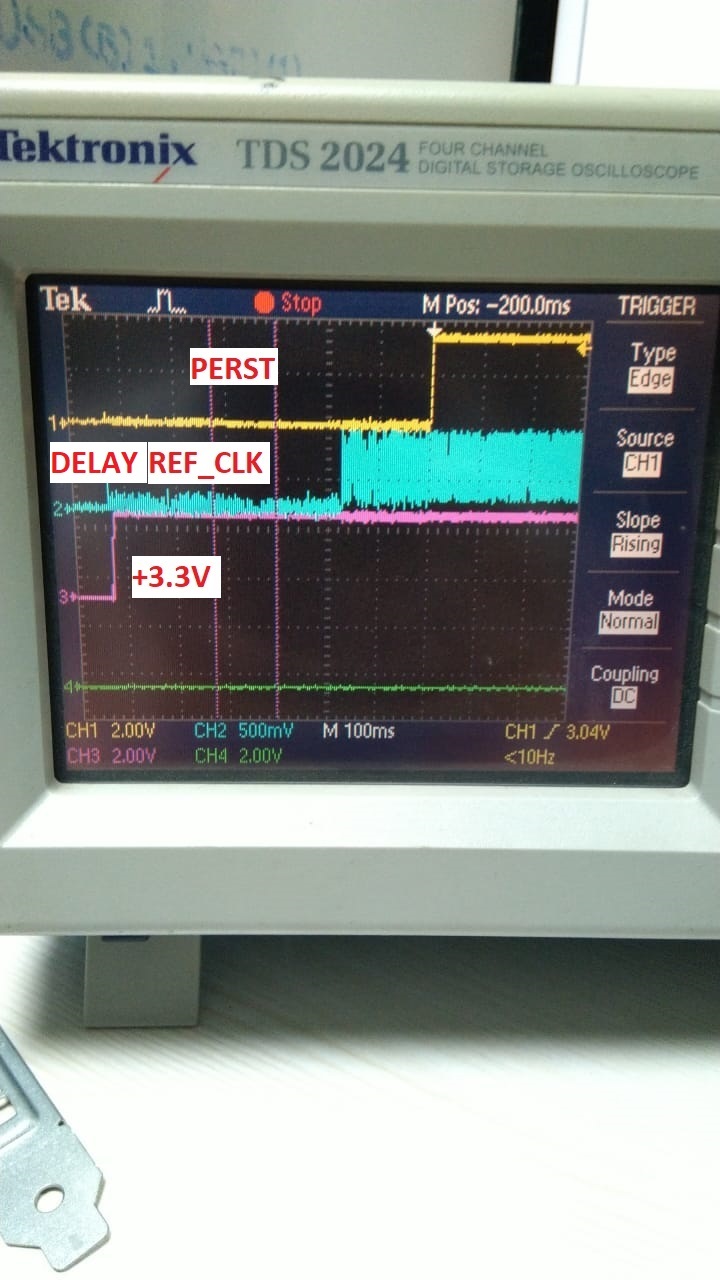
    As per your suggestion, we add some delay in REF_CLK but there is no any progress.

    Please find the attached Image for your reference.

    Does we have anything for read/write on EEPROM of EVM XIO3130? Which we can compare with our board result.

    Waiting for your earliest response.

    Regards,

    Alpesh


  • Hi alpesh,

    On the EVM, if you configure the EEPROM for normal mode operation does the issue still persist?

    Regards,
    I.K.
  • Hi I.K.,

    In EVM, In Normal & Express Mode the SCL and SDA of EEPROM consist High. So issue still persist.

    How we can Identify that EVM is properly Working as we are providing External Power Supply to it.

    We also connect the EVM to our Computer/PCIe Slot but in device manager we cannot find any activity. Only observation is that the Power supply LED is ON.

    Is there any software/utility to check the EVM ?

    Waiting for your response.

    Regards,

    Alpesh

  • Hi alpesh,

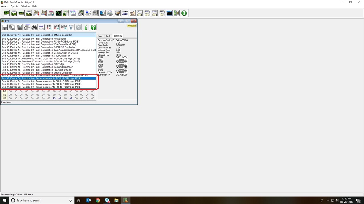
    I use a program called "RWEverything" (you can find a download through Google) to verify functionality of the EVM. When configured in normal mode operation, the XIO3130 should show up as three "Texas Instruments PCI-to-PCI Bridge" devices when plugged into a PCIe slot on the computer:

    Regards,

    I.K. 

  • Hi alpesh,

    Are you able to replicate my above post with the EVM on your system? The above is what you should see when the EVM is configured for normal mode operation, and is what I see in our lab.

    Regards,
    I.K.
  • Hi I.K.,

    Sorry for the late response as we faced issue with detection of EVM in PC so make changes in BIOS and resolve it.

    Now we get the same result as you mentioned. I have attached the Image for the same for your reference.

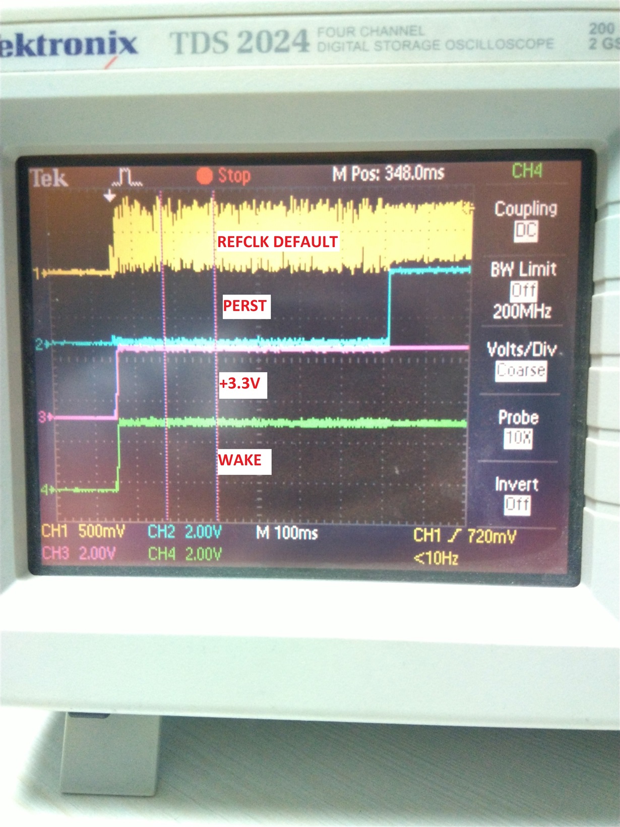
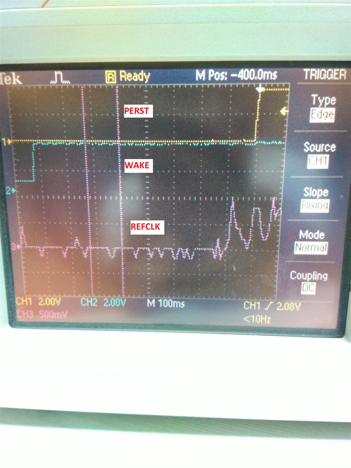
    I have also check the Signals between EVM and PC Mother board (PERST, REFCLK, WAKE). In which the sequence is like that : Wake(High) -700ms REFCLK - 100ms PERST(High). 

    Also check the same signal in our board and the sequence is like that : Wake (High) - same time REFCLK - 650ms PERST(High).

    Then make modification in CLOCK DRIVER and added delay in REFCLK using ARDUINO. Now the Sequence is like that :-  Wake(High) - 450ms REFCLK - 170ms PERST)High).

    Still there is no changes in Result and we are not able to detect the XIO3130 Switch.

    In EVM and Our Board, We keep the EEPROM in Normal Mode by Dip Switch and also Program EEPROM in Normal Mode. 

    I have attached the Images for each iteration here for your reference. 

    Note:- When EVM is connected to PC, Keep PC OFF then Supply +5V Externally to EVM and then Turn ON the PC to detect EVM. Without External (Delayed-After PC ON) Power Supply, EVM is not detecting by PC.

    Regards,

    Alpesh.

  • Hi alpesh,

    External power should be supplied to the EVM before the PC is turned on so that the datasheet power sequence is obeyed, so I believe that's expected behavior.

    In regards to the rest of your post, are you saying that you can see the XIO3130 in the RWeverything program on our EVM, but not on your own board? If this is the case I wonder if there's just an issue with the units you have on your boards. Would it be possible to swap the unit on the EVM with the unit on your board to see if the EVM starts showing issues and also to see if your board starts working correctly?

    Regards,

    I.K.

  • Hi I.K.,

    Thanks for the Response.

    Swap test is not possible in our Board because of BGA Package.

    We already share the Schematic file to Malik in private thread. We would like to second eyes to check the same, so can you please share your private thread to us?

    We will try to connect EVM to our Board by some another way and we will find that solution and keep you post.

    Observation:-

    In EVM, WAKE UP signal is going to Down stream port and Master where as in our board it is going to Down stream only. Is it required to connect with Master as it is Pull High signal?

    Waiting for your reply.

    Regards,

    Alpesh.


  • Hi alpesh,

    I have already received your schematic from Malik. So far it looks okay but I will continue to review it and let you know if I have any comments. Since you are able to get the EVM to work correctly I believe the issue is with either your board or with the units on your board.

    For the WAKE# signal, please reference section 3.8 of the implantation guide (www.ti.com/.../slla295a.pdf) for information about this signal. I believe it depends on your implementation.

    Regards,
    I.K.
  • Hi Alpesh,

    Have you been able to connect the EVM to your board? Without this or a swap test I am unsure of other ways to debug this issue.

    Regards,
    I.K.
  • Hi I.K.,

    Thanks for the Input.

    We are working on for connecting EVM to our Board. 

    Our prototype Board is ready so its hard to connect with EVM because of traces and connection so it will take little time.

    We will update you.

    Regards,

    Alpesh.

  • Hi alpesh,

    Any updates on this issue?

    Regards,
    I.K.
  • Hello I.K.,

    Thanks for the support.

    As per conversation with USA Aimtron Team, We will receive the samples of  XIO3130 by this weekend.

    We will perform the swap test in next week and keep you posted.

    Regards,

    Alpesh.

  • Hi Alpesh,

    Understood. Please also switch the position of the AC coupling capacitors on the TX/RX pins on the upstream and downstream ports. You can reference my last email to Dhaivat for those details.

    Regards,
    I.K.
  • Hello I.K.,

    Our Parcel is stuck in Custom Clearance and we are waiting for it.

    Once it received, we will perform the swap test and keep you posted.

    Regards,

    Alpesh.
  • Hi Alpesh,

    Any updates on this issue?

    Regards,
    I.K.
  • Hello I.K.,

    We have successfully performed swap Test but the result is same.

    Our Observation:-

    • We tried to follow up Power Sequence as per XIO2001 but didn’t get succeed result. 
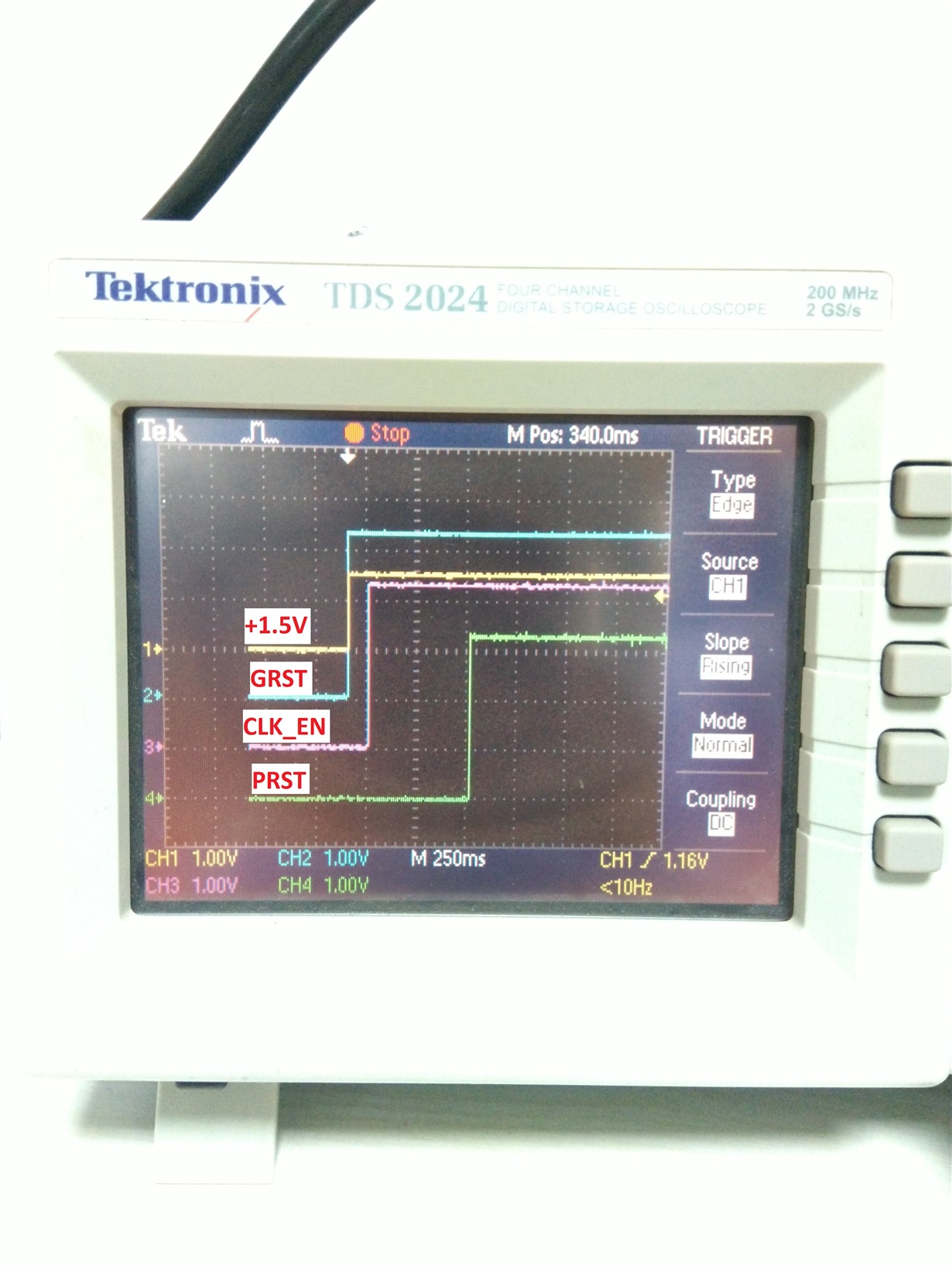
    • We are able to get the timing between 1.5V Power, GRST and CLKEN but not able to get PRST timing as that signal is controlling internally from Processor.
    • If we changing the timing span of GRST and CLKEN towards to PRST signal than we are able to get those timing, but 1.5V Power timing is more than mentioned in Datasheet. We observe in log that PCIE is Disable. Kindly Provide your thoughts.
    • As per XIO2001 datasheet, minimum timing requirement for PRST is 100mS after Power On, but more timing may be not an issue. Currently we are getting around 500mS on Scope, but still we are not succeed. Is is OK to have more than 100mS?

    EVM Observation:-

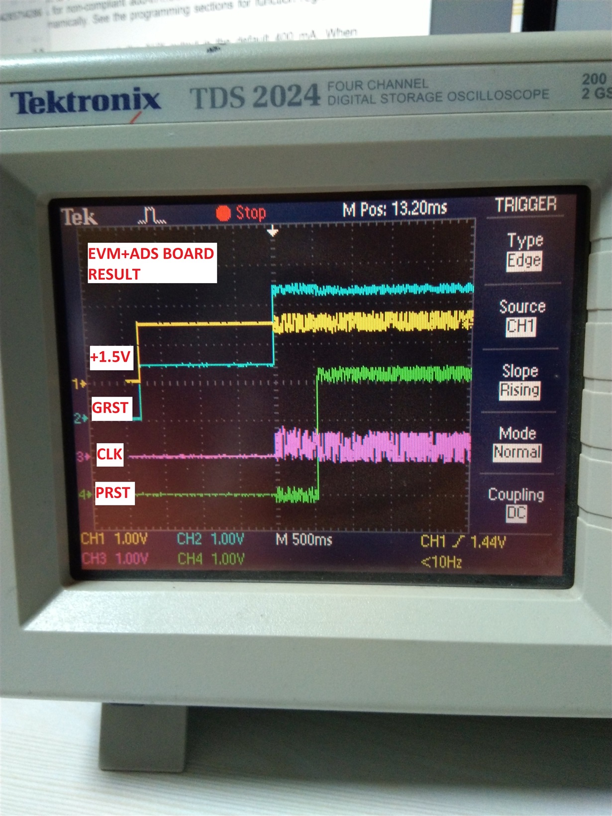
    • We have connected EVM-XIO3130 with Proto-Board and it can read EEPROM from EVM and Proto-Board can detect XIO3130 as PCIE switch. For timing, Please refer Image - EVM+ProtoBoard.jpg.

    Kindly Provide your feedback.

    Regards,

    Alpesh.

  • Hi alpesh,

    Is the 3.3V timing also correct for the power up sequence? In the 2nd scope screenshot there should also be at least a 100us delay between the REFCLK and PERST#. Also, it should be okay for PRST to de-assert after 500ms. 

    Additionally, per the email discussion, have you tried switching the position of the AC coupling caps on the TX/RX pins on the upstream/downstream ports on your board?

    Regards,

    I.k. 

  • Hello I.K.,

    • +3.3V and +1.5V are generating at same time as they are using common input supply, we have already verify on scope.
    • In second screen shot, each block is 100mS so REF_CLK and PRST is approximately 20mS.
    • Thanks for conforming PRST Timing.

    • For UP STREAM, AC Coupling Caps are on right Place (Near to the TX side of each Device).
    • For DOWN STREAM, We will change AC Coupling Caps for TX Line and Keep you Update.

    Meanwhile if you find anything, Please keep us posted to moving forward.

    Regards,

    Alpesh.

  • Hi Alpesh,

    Do you have any updates on the results of switching the AC coupling caps on the downstream port?

    Regards,
    I.K.
  • Hello I.K.,

    First we are trying to Detect XIO3130 Switch with EEPROM on Up Stream Port.

    Is it required to Change the AC Coupling Capacitor on Down Stream Port to Detect XIO3130 Switch with EEPROM? 

    Kindly Provide your input for the same.

    Regards,

    Alpesh.

  • Hi Alpesh,

    I am not sure if it will have an effect on detecting the EEPROM, but incorrect AC coupling capacitor placement would cause issues regardless, so it is worth ensuring the placement is the same as depicted by our EVM.

    Also, would it be possible to swap the EEPROM you have on your board with the EEPROM on the EVM (i.e. take the EEPROM on the EVM and put it on your board)? I don't know how difficult this would be to accomplish but it would help to confirm whether or not there's an issue with your EEPROM itself and narrow down the root cause. So far we've established that there's no issue with the units, and after you switch the AC coupling caps we can establish that there's no issue with the circuit. At that point I believe it just leaves the EEPROM.

    Regards,
    I.K.
  • Hello I.K.,

    We did swap test for EEPROM but we got same result, did not get success result. For swap test we used EVM Board EEPROM.

    For Down Stream AC Coupling, we are changing in our board as per Guideline and will keep you posted.

    Regards,

    Alpesh.