Other Parts Discussed in Thread: BQ25895
Hi, Team
the following is our project information:
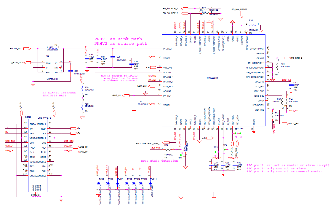
1. Our project is a power bank, MCU communicate TPS65987D via I2C bus
2. TPS65987D as DRP role . External sink charges the battery through PP1_HV1, sink capabilities are 5V/3A and 9V/2A; Source charges external devices through PP2_HV2, source capabilities are 5V/3A and 9V/2A.
3. Our project TPS65987D does not have an external SPI Flash.
4. The MCU's internal flash used by our project is only 8K. There is no enough space to transfer the patch bundle and configuration to the TPS65987D by PTCx command set(4CC) via I2C;
The original design idea is that the MCU writes the configuration generated by the TI configuration tool (TPS65987D I2C register), which contains some mapping of GPIO events.
For example, the PD_SOURCE_1 output is high when the 5V/3A source is plug in, and the PD_SOURCE_2 output is high when the 9V/2A source is plug in. When the PD is the Sink, the PD_SINK_1/PD_SINK_2 is used.
However, we found that the GPIO IO Config (0X5C) register is read-only to the external HOST (MCU) and cannot be written, that is, PD_SOURCE_1/PD_SOURCE_2, PD_SINK_1/PD_SINK_2 cannot work as we intended.
So our current practice is that the MCU writes the configuration generated by the TI configuration tool (TPS65987D I2C register) and the I2C1 event configuration. When the corresponding PD event occurs, the PD notifies the MCU through I2C1_IRQ, and the MCU query the TPS65987D register (such as Status 0x1A, PD Status 0x40, Active PDO, Active RDO, etc.) via I2C to obtain the current (Source/Sink) and corresponding negotiated voltage and current of the TPS65987D, then do setting operation to the back end, for example, when PD act as Sink role, configures the charging current of TI BQ25895, and the source regulates 5V or 9V.
At present, the BUSPOWER (ADCIN1) configuration on our PCBA is 0.9, that is, Configuration 5, the TPS65987D can normally find the capability of the Type-C power adaptor; however, when connecting a mobile phone or a DRP power bank, the PD protocol’ negotiation of the TPS65987D is abnormal. The PD Controller is acting like a legacy sink or source. The ability to discover the connected device is incorrect.
Does our design idea conform to the working mode of TPS65987D? The attachment is the TI Customization Tool configuration file and circuit diagram. Please help check and analyze, thank you!


