This thread has been locked.

If you have a related question, please click the "Ask a related question" button in the top right corner. The newly created question will be automatically linked to this question.

DS90UB954-Q1: using gpio pin output control to show status of csi2 tx port

Part Number: DS90UB954-Q1

Hi ,

trying to understand the table8 of the datasheet for monitoring csi 2 tx port , some text has unfinished (note)

we set 2 gpio to see rxo and rx1 frame valid pulse on scope , 3rd gpio to try and monitor ex ports sync output as follows.

print "monitor the 954 sync pulses and sync out ok      "
board.WriteI2C (UB954,0x0f,0x78) # 3 gpio as outputs
print "monitor the rx0 sync pulse on gpio 0   "
board.WriteI2C (UB954,0x10,0xc3) # gpio0 rx0 frame sync
print "monitor the rx1 sync pulse on gpio 1 "
board.WriteI2C (UB954,0x11,0xc7) # gpio1 rx1 frame sync
print "monitor the csi-2 TX port       "
board.WriteI2C (UB954,0x12,0xb1) # gpio2 synchronous OK

get the frame valid pulses on scope ok but not sure if the 3rd I/O is setup ok .

Any comments ?

  • Hi Martin,

    Currently on GPIO2, you have it set to output Device Status - Device Interrupt Active High. Could you clarify what you'd like GPIO2 to do?

    Best,

    Jiashow

  • We have 2 off 1920 x 1080 yuv422 bit streams that we are trying to line concatenate.

    Would like to monitor the equivalent of the reg 0x25 and 0x22 bits that show that both ports are in sync , on a scope .

     so does the setting

    RX Ports synchronized, RX Port 0 synchronized with RX Port 1 : bit pattern 101 100 x 1 in reg 0x12 achieve this , and is it active high output if true ?

  • Hi Martin,

    You are correct, if you want GPIO2 to indicate whether RX port 0 is synchronized to RX port 1, set GPIOC_OUT_SEL to 100, GPIOX_OUT_SRC to 101, GPIOX_OUT_VAL to 0/1 (x), and GPIOX_OUT_EN to 1.

    Just a reminder, GPIOx Register Conctent (reg 0x10 - 0x16) is as follows:

         [7:5] = GPIOX_OUT_SEL (100)

         [4:2] = GPIOX_OUT_SRC (101)

         [1] = GPIOX_OUT_VAL (x)

         [0] = GPIOX_OUT_EN (1)

    This GPIO should be on if RX0 is synchronized to RX1.

    Best,

    Jiashow

  • Hi , so setup the 3 gpio to monitor frame valid signal from RX port 0 , the frame sync signal form dvice status register and csi 2 port rx port 0 synched with rx port 1

    board.WriteI2C (UB954,0x0f,0x78) # 3 gpio as outputs

    board.WriteI2C (UB954,0x10,0xc1) # gpio0 rx0 frame sync

    board.WriteI2C (UB954,0x11,0x91) # device status register frame sync

    board.WriteI2C (UB954,0x12,0x95) # csi 2 rx port 0 sync with rx port 1

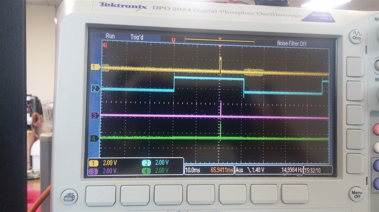
    what I observe on scope triggered on frame sync from 953 serialiser is

    yellow trace frame sync  

    cyan trace is rx port 0 frame valid signal

    purple and green traces are from the sensor strobe frame sync signals

    I am confused about the RX port frame valid signal as I assumed it would track with the start of the frame sync signal pulse .

    Could someone explain what the pulse represents in this regards

    I am trying to get the two ports to achieve line concatenation and thought that everything aligned to the frame sync pulse start would be sufficient for this .

    any further suggestions appreciated

  • Hi Martin,

    The frame sync signal is supposed to indicate when a frame is being transmitted. Can you verify if the sensor is synchronized to the framesync signal? Can you check both RX0 and RX1 frame valid to see if the two sensors are synchronized?

    Best,

    Jiashow

  • yes , the sensors are synchronised to the 953 frame sync signal and also both frame valid signals are the same on the scope traces when i set gpio 0 amd gpio 1 to reflect frame valid 

  • Took more scope screen grabs with GPIO set as follows


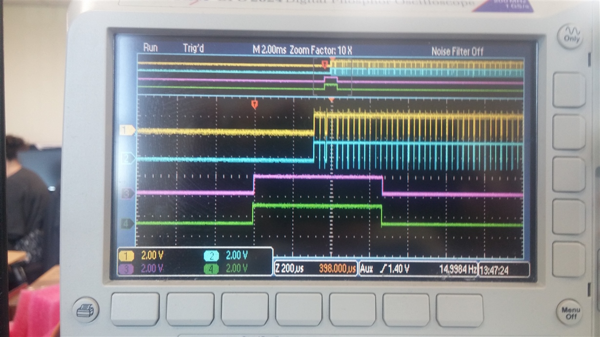
    board.WriteI2C (UB954,0x10,0xe5) # gpio0 rx0 line sync : yellow trace

    board.WriteI2C (UB954,0x11,0xe5) # gpio1 rx1 line sync : cyan trace

    board.WriteI2C (UB954,0x12,0x91) # gpio2 synchronous csi 2 transmitter   : green trace

    the purple trace in the first picture is the frame sync pulse

    ALL traces synced to sync pulse signal generated from DS90UB954 and output form the 2 DS90UB953 serialiser to the image processor chips

    You can clearly see that LV outputs are in sync and that the green trace [RX Ports synchronized, RX Port 0 synchronized with RX Port 1] is synced with the sync pulse.

    Why is this ?

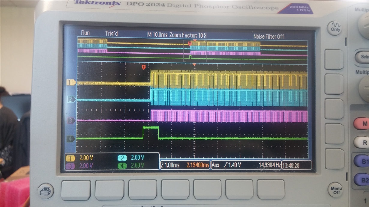
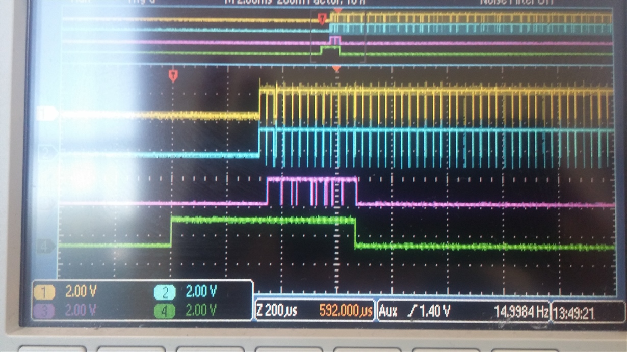
    So the next picture shows the same signals except that purple is now the line valid output debug pin signal form a mipi to usb3 encoder device . Here the system is set for line concatenate with only port 0 or port 1 active in RX port forwarding control register.

    here we get the expected 1920 x 1080 yuv 422 8 bit output displayed on pc

    Now when we set both ports are active in RX port forwarding control register , we get the LV signals form the MIPI to USB3 chip terminate as the frame sync and CSI2 RX ports aligned signals go low.

    so does the CSI2 RX ports aligned output track with the frame sync pulse ?

  • changed the frame sync to 50:50 and the csi2 rx ports locked does track with the frame sync signal.

    ################################################################################
    # setup 50: 50 : fsync
    ################################################################################
    board.WriteI2C (UB954,0x1a,0x00)
    board.WriteI2C (UB954,0x1b,0xd9)
    board.WriteI2C (UB954,0x1c,0x1c)
    board.WriteI2C (UB954,0x18,0x03)

    so in  the frame concat mode  , the cx3 seems to truncate at the same point above relative to frame sync start and halt at about  300uS after the start.,

  • Hi Martin,

    I don't think the framesync signal has to necessary align with line valid. It is just a pulse wave to allow the sensor to determine when to send the sensor data. As long as the two sensors are aligned, which is the case, your system should be working properly.

    Best,

    Jiashow

  • I am not certain that the sensor are aligned enough , the purple trace shows only a couple of concatenated lines before output stops , is this the full output of the 954 line buffer ?

    the USB3  debug shows only a frame size of 46088 bytes per frame during line concat mode

  • Hi Martin,

    Can you check register 0x22 to see if the device tells you whether or not the sensors are synchronized?

    Best,

    Jiashow

  • using this code

    for x in range(0,2000):
        print " sync register ",hex(board.ReadI2C(UB954,0x22,0x01))

    when in line concat mode but just on port active we get 0x01 , when both ports set active via port forwarding control we get 0x00

    so not in sync as far as the DS90UB954 is concerned

  • Hi Martin,

    It doesn't seem like the two sensors are synchronized. How are you sending your frame sync signal? Do your sensors have any requirements for the frame sync?

    Best,

    Jiashow

  • Hello Martin,

    Any feedback here? Is the issue resolved?

    Best Regards,

    Casey 

  • Hi , 

    We had to dig deeper into the sensor ISP mipi settings and by changing THS exit parameter we are able to get 720p concatenation .

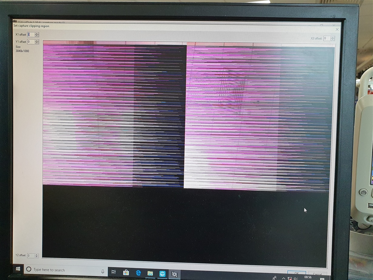
    The goal is still to get 1080p and what we observe at present is that the first 14..16 lines are ok then the image starts to streak with banding . 

    We believe that this is in the mipi to usb  converter device and not any 954 setting per se .

    Will attach screen grabs later , showing the artefacts in case anyone has observed something similar.

    regards 


  • Attached is the displayed output .

  • We updated the ISP firmware to allow a mode that throttles back the data and this worked.

    We now have the 3840 x 1080 concatenation at 20 IPS