This thread has been locked.

If you have a related question, please click the "Ask a related question" button in the top right corner. The newly created question will be automatically linked to this question.

SN65DSI85-Q1: SN65DSI85 output is abnormal

Part Number: SN65DSI85-Q1
Other Parts Discussed in Thread: DSI-TUNER

Dear team,

The oscilloscope measurement is used to find that the DSI85 input signal is normal, but one of the output terminals has no video signal output while has the backlight.

At this time, read CSR 0xE5 and CSR 0xE6, their value are all 0x00 which means no error detected.

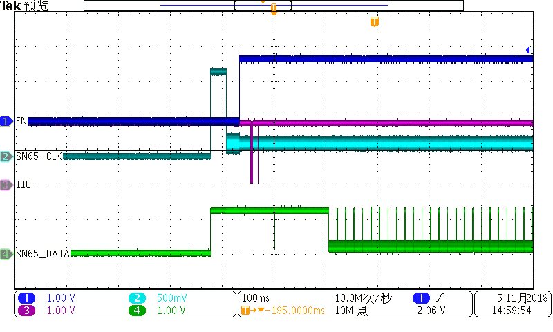
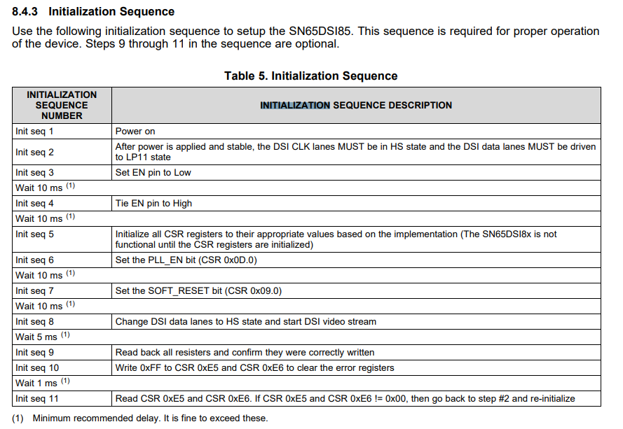
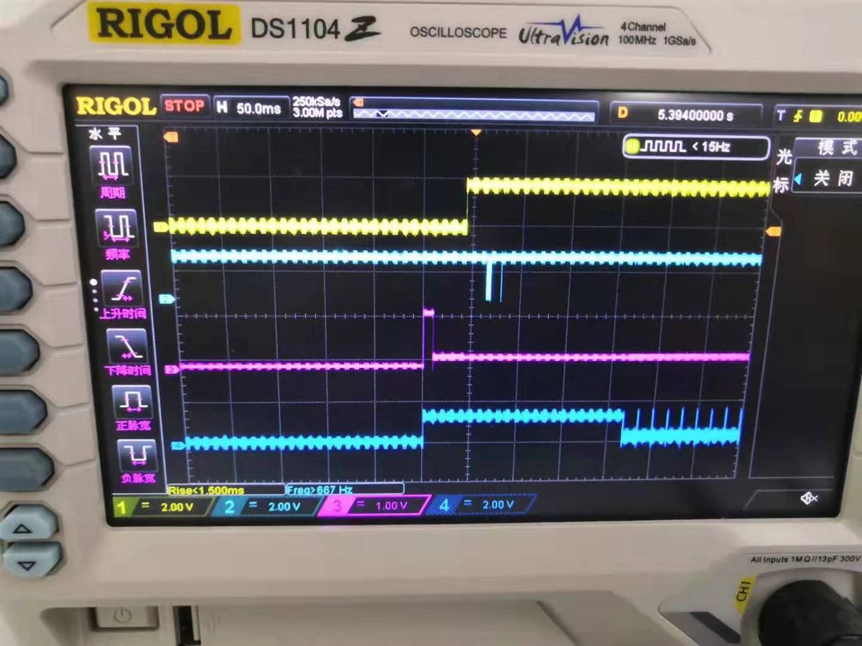
In addition, the power on sequence is as below, is there any problem about it?

Thanks & Best Regards,

Sherry

  • Hi Sherry,

    The sequence looks okay. Can you also confirm that the PLL is enabled only after configuring all of the DSI85 registers, and that the DSI data lanes are switched to HS only after the PLL is enabled? I can't tell from the screenshot.

    Additionally, what is the operating mode of the DSI85? Is it two independent DSI inputs to two independent LVDS outputs?

    Regards,

    I.K. 

  • Hi I.K.

    The customer is referring to below sequence, and they have done the 1-8 steps.

    About the operating mode, I need to confirm to the customer.

    Thanks & Best Regards,

    Sherry

  • Hi Sherry,

    Any updates? Is this issue still open?

    Regards,

    I.K. 

  • Hi I.K.,

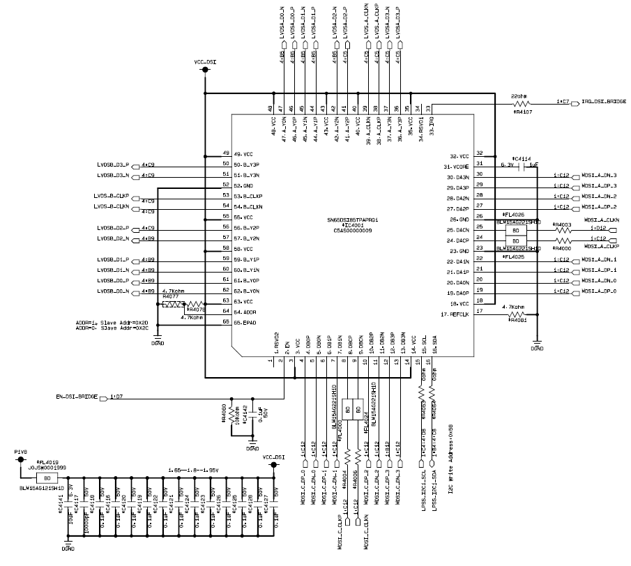
    The schematic is as below, please check it!

    Thanks & Best Regards,

    Sherry

  • Hi I.K.,

    The working mode is Dual DSI Inputs(two streams) to two Single-Link LVDS.

    Thanks & Best Regards,

    Sherry

  • Hi Sherry,

    The schematic looks okay. It's strange that one screen works and the other doesn't. Which channel is not working (A or B)? Can you look at the output LVDS CLK on an oscilloscope to see if there's any clock output for the screen that's not working?

    Regards,

    I.K. 

  • Hi I.K.,

    Sometimes A channel doesn't work, sometime B channel doesn't work, and sometimes both A and B channels don't work. When the fault occurs, there are no clock and data output.

    Almost all the devices have this fault which will appear as long as you restart them many times.

    Thanks & Best Regards,

    Sherry

  • Hi Sherry,

    Does this issue only occur on power-up or restart? Namely, if a channel comes up correctly there will be no issues with it as long as the device is not restarted? 

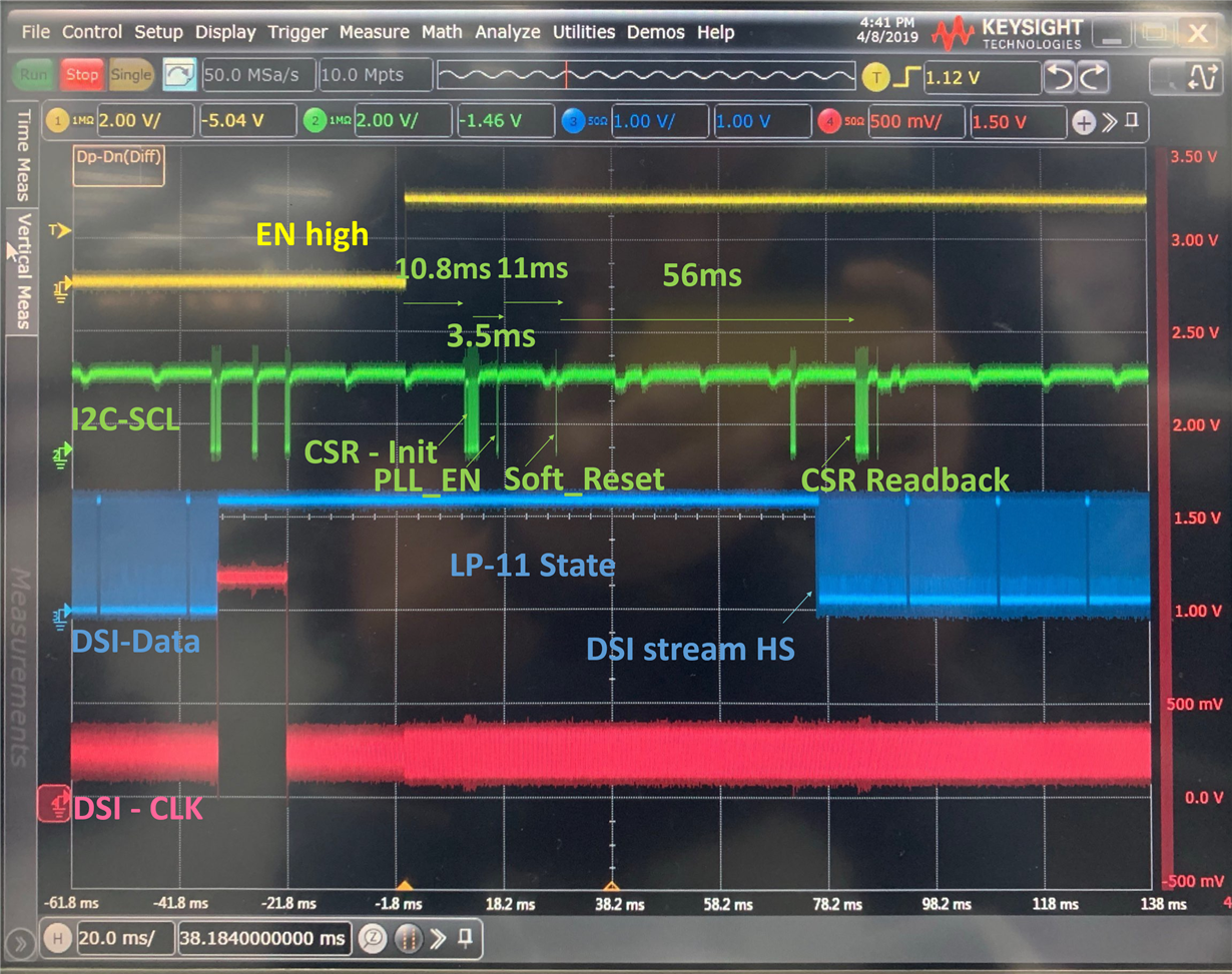
    If so, this is very likely an initialization sequence issue. Please share a more detailed and labeled oscilloscope screenshot of the initialization sequence like below:

    Please also note that for restarting, there is a required sequence "Video STOP and Restart Sequence" in the datasheet. Please ensure they are also following this sequence. There is a typo in step 3 of that sequence though. It should say that all the DSI input lanes must be driven to LP-11 except the DSI CLK. The DSI CLK must remain in HS the entire time. 

    Regards,

    I.K. 

  • Hi I.K.,

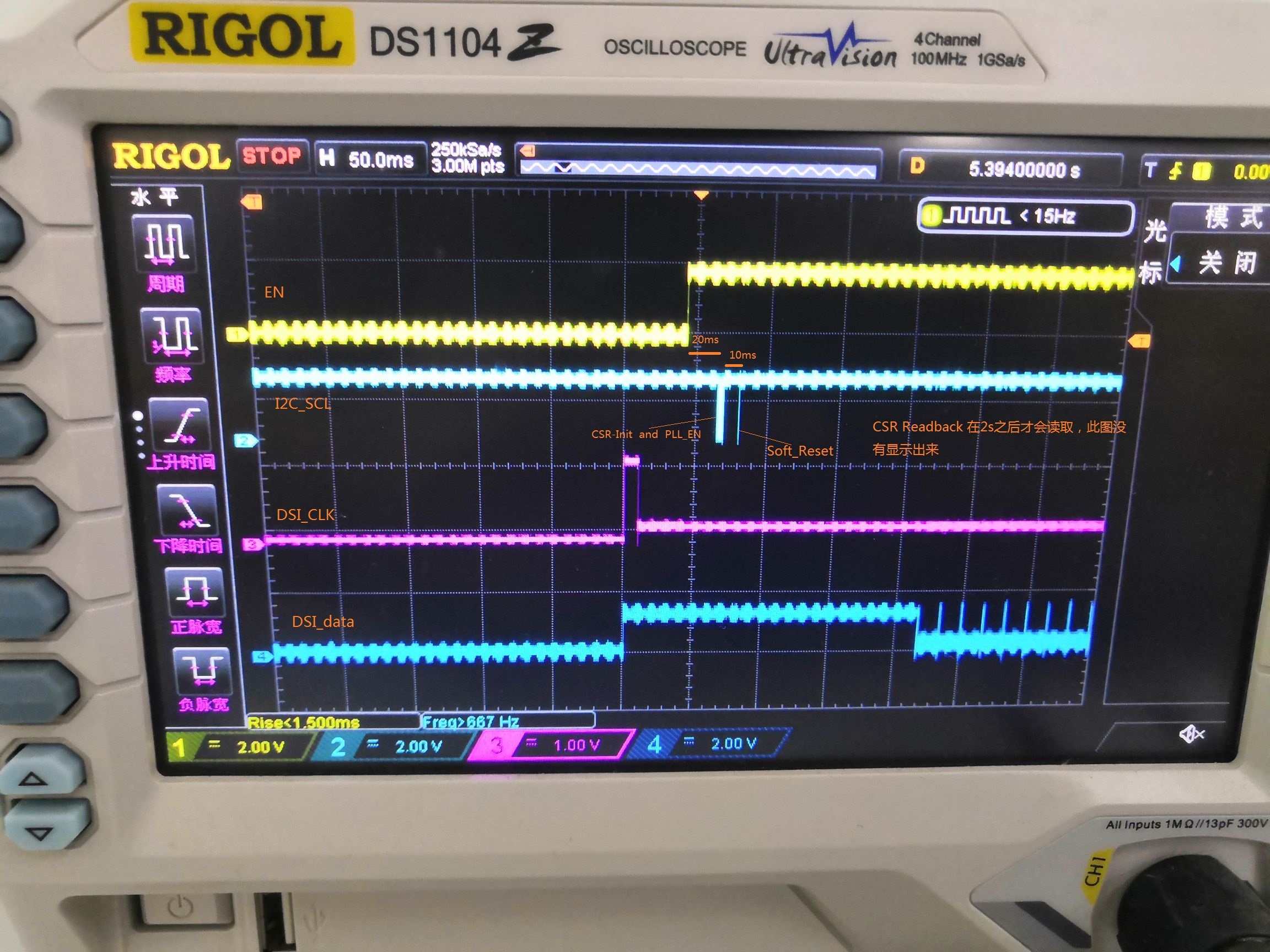
    The detailed initialization sequence is as below: from up to down: EN, I2C_SCL, DSI_CLK, DSI_DATA.

    The description I said before is a little not clear. Once the fault happens when first powering up, then this fault will re-occur if you restart it many times, but if the fault doesn't happen at first powering up, then this fault won't happen even though you restart it many times.

    In addition, due to the limit of the MCU, they can't meet the restart sequence requirement. But I think this fault is not related to the restart sequence, it depends on the first power up.

    Thanks & Best Regards,

    Sherry

  • Hi Sherry,

    This still points to an initialization issue. Please provide a more detailed scope capture like the example I provided in my previous reply. For example, the waveform you provided does not say when or where in the sequence the PLL is enabled. 

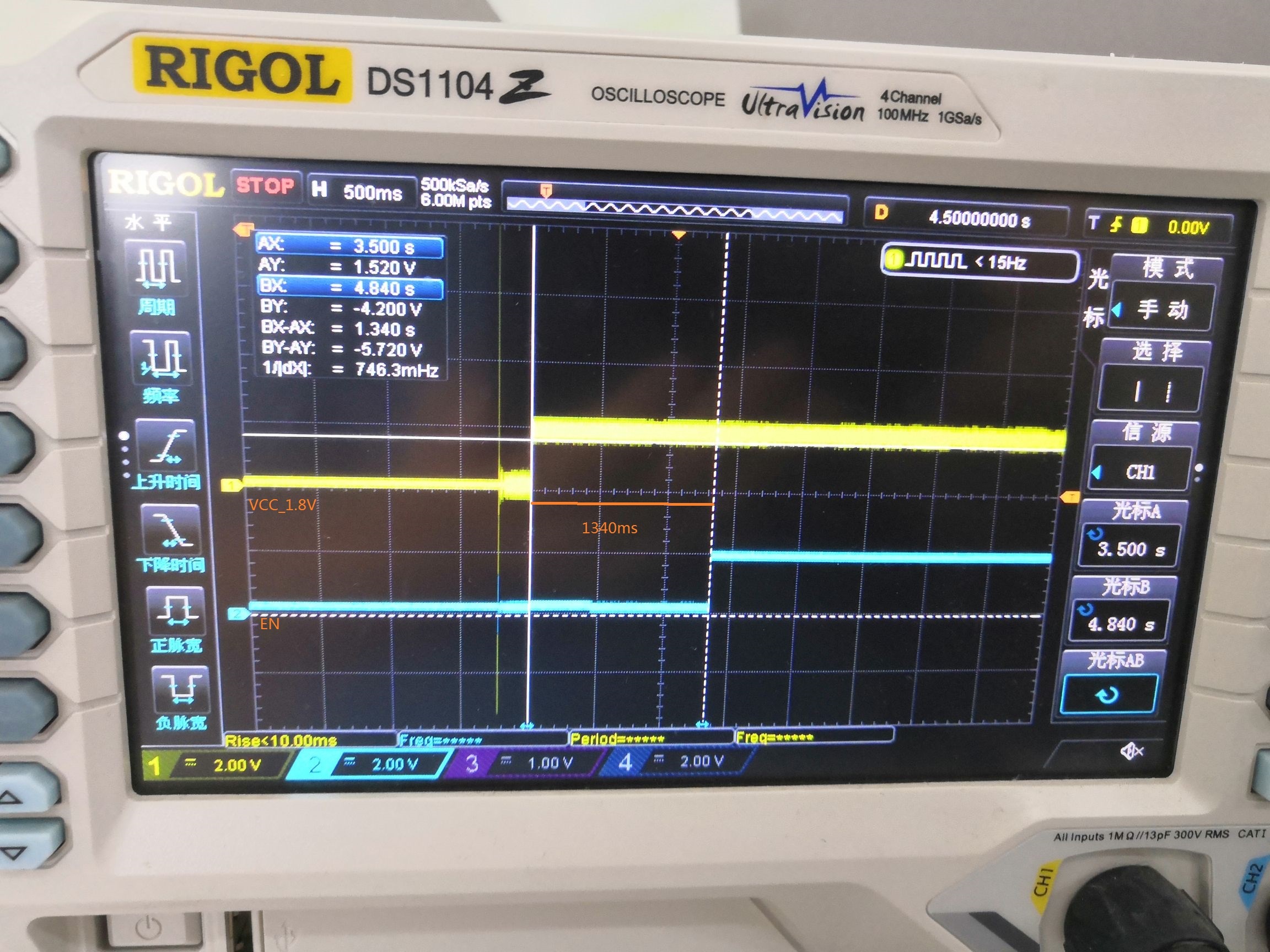
    Additionally, have they ensured that the EN pin is low for at least 10ms after Vcc is stable high at 1.8V?

    Regards,

    I.K. 

  • Hi I.K.,

    Please check below waveform, CSR Readback will be read after 2s, this picture doesn't show this.

    Thanks & Best Regards,

    Sherry

  • Hi Sherry,

    How much noise is present on Vcc? Is it less than 50 mVpp? 

    In regards to the issue, in the case when both displays go out and there is no output clock seen on both channels, does register 0xE5 really read 0x00? If there is no output clock then the PLL_UNLOCK bit should be getting set. Please double check by reading the register only after the video has gone out on both displays (and clear this register by writing 0xFF to it before reading from it). Also, what is the status of register 0x0A and 0x0D in this case? Have they checked the DSI inputs to see if there were any changes in the DSI clock and DSI data?

    Also, as another test, can they try replicating the issue when the device is configured for test pattern mode?

    Regards,

    I.K. 

  • Hi Sherry,

    In addition, can you please clarify your previous statement: "In addition, due to the limit of the MCU, they can't meet the restart sequence requirement."?

    What do you mean by this? Are they not following the stop and restart sequence?

    Regards,

    I.K. 

  • Is this issue still open? 

  • Hi I.K.,

    Yes, I will update this on Monday.

    Thanks & Best Regards,

    Sherry

  • Hi I.K.,

    1. The noise on the VCC is smaller than 40mVpp;

    2. In the event of a fault, the 0xE5 register is 0x00; each time 0xE5, 0xE6 is read, write 0xFF first to clear the register, and after 5ms, the register value is read;

    3.About the 0x0A and 0x0D, I will update later;

    4. They have checked the inputs of DSI when fault occured, but there is no change in the DSI clock and DSI data;

    5. I don't see the description about how to enter test pattern mode in the datasheet. Could you please tell me?

    Thanks & Best Regards,

    Sherry
  • Hi Sherry,

    The test pattern is described in section 8.3.8 of the datasheet. You can get the register settings by using the DSI-Tuner. 

    Also, please clarify what you mean when you say the customer can't  meet the restart sequence requirement. Are they not following the stop and restart sequence?

    Regards,

    I.K. 

  • Hi I.K.,

    1. Ok, I will let the customer try the test pattern.

    2. Yes, they are not following the stop and restart sequence. But the fault always occur at the first power on. Once the first power on, failure occurs, then restart, the fault is easy to reoccur. But if the first power on, no failure occurs, then restart, this failure is very hard to reoccur.

    Thanks & Best Regards,

    Sherry
  • Hi Sherry,

    Just so we're on the same page, please explain in detail how exactly they are restarting the device.

    Additionally, it seems like there is a difference between consecutive power on's if a fault occurs in one instance but no fault occurs in another. They will need to investigate what the difference is between the power ons where a fault occurs and where one doesn't (e.g. initialization sequence, DSI CLK quality/stability, etc.)

    The test pattern should also help with the debug as the only input it takes from the DSI side is the DSI CLK.

    Regards,

    I.K.