This thread has been locked.

If you have a related question, please click the "Ask a related question" button in the top right corner. The newly created question will be automatically linked to this question.

DS90UB953-Q1: I2C no response

Part Number: DS90UB953-Q1

HI TI employees

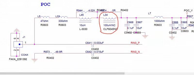
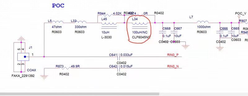
We used ds90ub953/954 to design the camera scheme, but we found that sometimes I2C did not respond. Our design drawing is slightly different from the reference design of TI, in which the large inductance of 100uH is not added, is it possible that this is the cause of this problem

  • Hello,

    The PoC filter design is critical for FPD Link III so it is possible that your problem could be related to the PoC network. The 100uH inductor is usually only recommended for "2G" operation though or when the back channel is at a lower frequency than 50Mbps. Can you please share your PoC network design so we can review? Also what operational mode are you using 953/954 in? Synchronous or non-synchronous?

    Best Regards,

    Casey 

    • My schematic is as follows,however, I found that the 100uH inductance in the figure was added, and occasionally I2C did not respond.  Is there a difference between RX0 and RX1 in 954EVM? What's the point.

  • I found that whether I add 100uH  inductor or not, I will lose I2C, which is from 954 to CPU

  • Hello,

    Yes there is a difference between RX0 and RX1 on the 954 EVM. RX0 is meant to pair with the 953 EVM and RX1 is meant to pair with the 933 part. Note with the actual device, you can use either input for the 953 or 933, only the EVM makes a distinction.

    The reason for this is because the older 933 device has a lower back channel frequency, which means the POC circuit is different. Please refer to figure 5 and 6 in the 954 EVM user guide. You must ensure you have the proper network for the device yo are pairing with.

    User guide link: http://www.ti.com/lit/ug/snlu223/snlu223.pdf

    Can you confirm that adding this inductor has no impact on whether you lose I2C or not?