This thread has been locked.

If you have a related question, please click the "Ask a related question" button in the top right corner. The newly created question will be automatically linked to this question.

DP83TC811S-Q1: Problems with communication

Part Number: DP83TC811S-Q1

Hi Guys,

I'm working on a 100Base-TX to 100Base-T1 converter as an university project, which uses the DP83TC811S. I developed a prototype, that uses a direct connection with RMII between the two PHYs KSZ8081RNA (100Base-TX) and DP83TC811S (100Base-T1). I attached my schematic and the programming of the registers of the PHYs by using SMI over a STM32F107RC (with STM32CubeIDE). The Hardware seems to be working, the PHYs seem to communicate with each other and a communication between two converters with 100Base-T1 seems to be working too (synchronous LED_1 blinking).

/cfs-file/__key/communityserver-discussions-components-files/138/SPE.pdf

/cfs-file/__key/communityserver-discussions-components-files/138/main_5F00_master.pdf

/cfs-file/__key/communityserver-discussions-components-files/138/main_5F00_slave.pdf

My Problem with the project is that, when I connect two converter and use them as a bridge between my PCs, a communication cannot be achieved. I used Wireshark to see what's going on, but the only thing I see is that the PCs are trying to communicate, but cannot achieve a IP exchange. (I attached some screenshots)

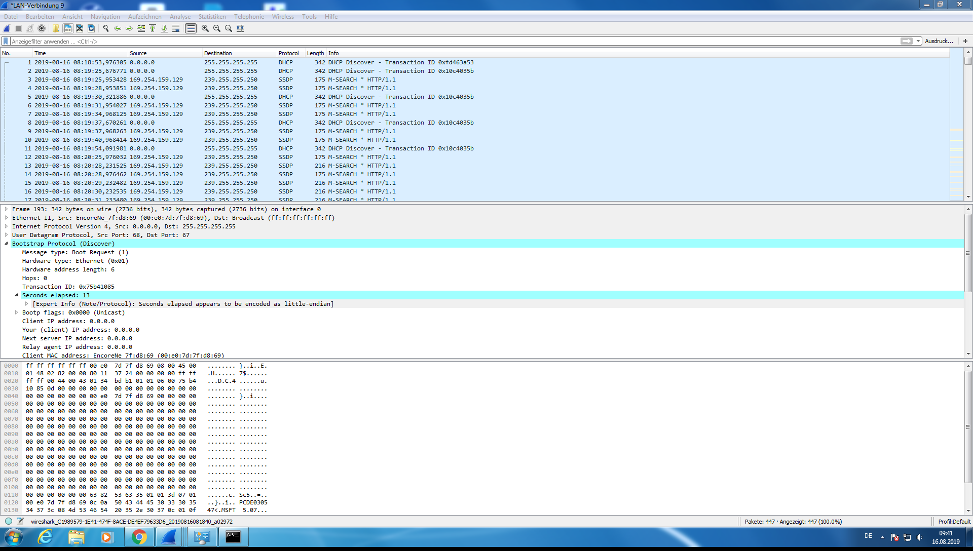
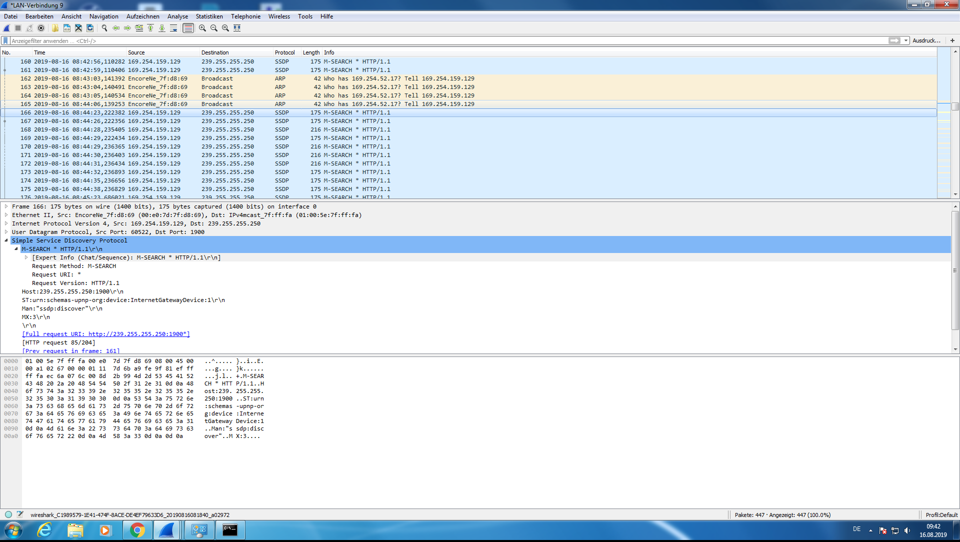
What is the problem in this application and what needs to change at the prototype in order work properly. I can only think of a problem in the settings of the register of the PHYs or the communication between the PHYs.

I'm a student and I cannot think of any solution for the problem with my knowledge. I hope that somebody can solve the problem or at least explain what's wrong!

Thanks a lot!!

  • Hi Tobias,

    For RMII, the PHY will use CRS_DV and with that you see a toggle at the end of the frame.

    If you are using back-2-back method, that toggle cannot be used.

    Please either configure RMII to version 1.0 through register 0x17 or set register 0x47D bit[2] to 0 instead of 1.

    1 = CRS_DV

    0 = RX_DV

  • Hi Ross,

    unfortunately your suggestion didn't solve my issue.

    I tried both variations and both don't seem to be working.

    Do you have other tips or possiblilities of a solution?

    Best regards,

    Tobias

  • Hi Tobias,

    Can you please send me a register dump of 0x0 to 0x1F as well as 0x133, 0x467, 0x196 for the 811 devices please?

    Do you have an oscope on hand? I suggest you probe TX_EN, RX_DV and RX_ER to see if you see traffic on both media converters when sending pings.

    See if the length of those TX_EN and RX_DV assertions are the expected bit lengths of the frames transmitted.

  • Hi Ross,

    I'm sorry it took me so long to answer. Our Highspeed-oscope was away for calibration.

    I did what you asked for. I measured TXEN, CRSDV, RXER and I created a register dump (files are in the .zip). I didn't use RXER in the application, so it's not connected to anything. I thought it was optional and not required.

    But I don't quite understand how I can check the expected lengths of the frames. I sended a 32 byte package per pinging and the Signals were asserted for about 8 microsecs. I would  be kind of you, if you can explain, how to do that. I'm a electrical engineering student and would like to know those things for my future;)

    Best regards,

    Tobias Jehle

    /cfs-file/__key/communityserver-discussions-components-files/138/TI_5F00_Ross_5F00_SPE.zip

  • Hi Tobias,

    I see TX_EN toggling in the scope captures for both Master and Slave. 

    Are the TX_EN plots from KSZ to 811 or from 811 to KSZ? 

    TX_EN must not toggle at the end of a frame. If it does, that means the device is operating in RMII revision 1.2 and not RMII 1.0.

    Also, from the register dump it looks like 0x17 is set to 0x40F0, which means the PHY is in RMII revision 1.0.

    There are reserved bits also being set.