Other Parts Discussed in Thread: AM5728, TPS659037, PMP
Hello,
we are developing for a customer a custom board based on TI AM5728 controller and experiencing now such a problem that Ethernet PHY DP83867E is not visible in u-boot (all PHY register reads return 0xFF92 value). The PHY is used in RGMII mode.
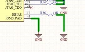
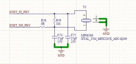
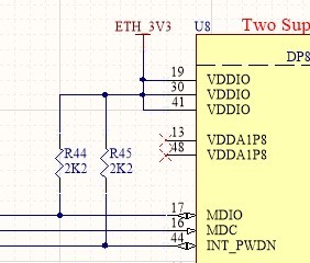
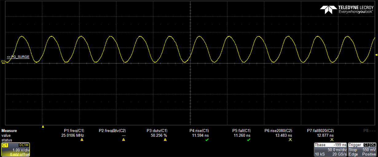
Our hardware engineers checked, that all voltages (3.3V, 2.5V and 1.0V) and 25 MHz frequency are present, pins RESET_N and INT/PWDN are set high, MDIO pin is pulled-up according to the datasheet. Both pins GPIO_0 and GPIO_1 are isolated. RBIAS has 11k resistor on it (see below).
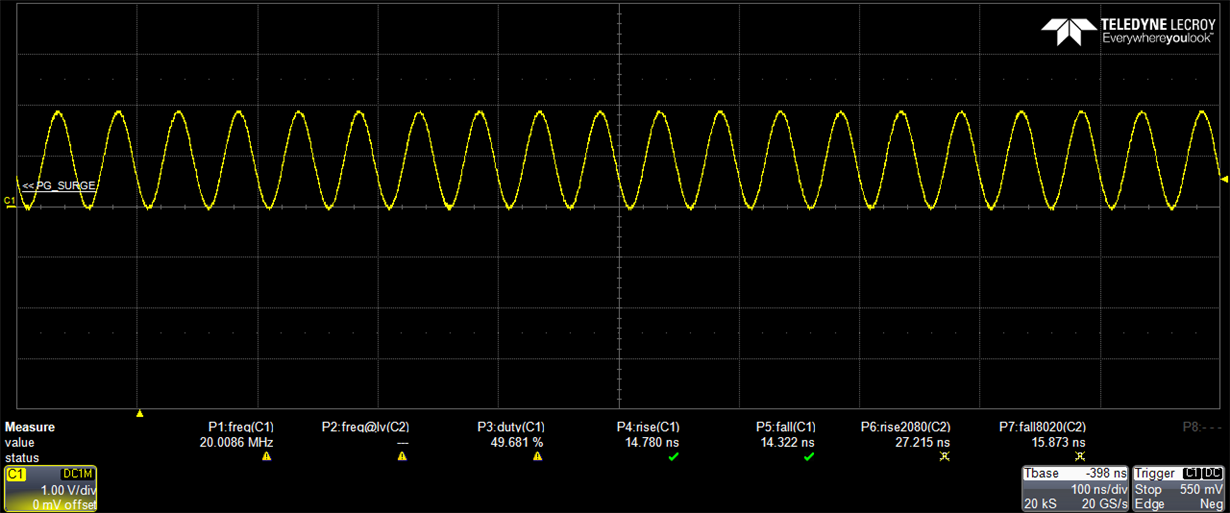
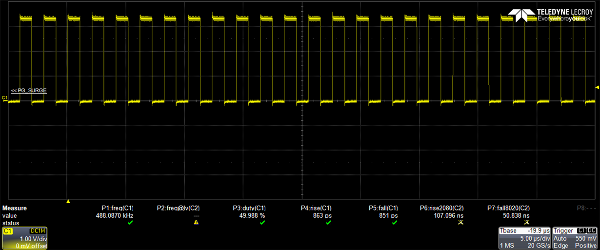
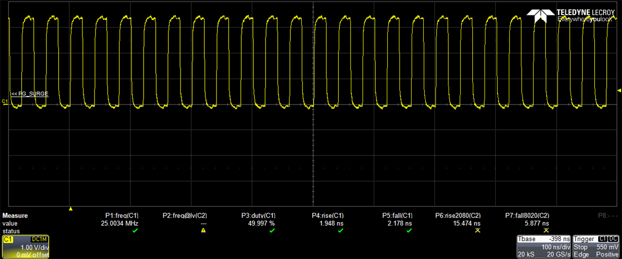
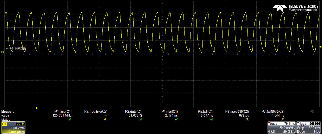
The reference frequency 25 MHz is sourced like here
MDIO pin is pulled-up with 2.2k to VDDO 3.3V like here
We are using ti-processor-sdk-linux-am57xx-evm-05.02.00.10 and below you can see u-boot startup console output (I also added some additional prints).
Attached you find board-specific device-tree files and complete device-tree generated during u-boot building.
We need a solution for the problem very urgently and look forward hearing from you as soon as possible.
Best regards,
Timur Perekhodko.
U-Boot 2018.01 (Aug 16 2019 - 11:54:29 +0200)
CPU : DRA752-GP ES2.0
Model: red-ant VAU P3
Board: red-ant vau-p3 rev A
DRAM: 2 GiB
vau-p3/board_init: CONFIG_SYS_SDRAM_BASE + 0x100
MMC: OMAP SD/MMC: 0, OMAP SD/MMC: 1, OMAP SD/MMC: 2
vau-p3/board_late_init
vau-p3/setup_board_eeprom_env
check TPS659037_POWER_SMPS7_CTRL_MODE_OFF
check TPS659037_POWER_SMPS7_VOLTAGE_2_5_V
check PS659037_POWER_SMPS7_CTRL_MODE_ACTIVE | TPS659037_POWER_SMPS7_CTRL_WM_INSENSITIVE
vau-p3/set_board_info_env: TPS659037_POWER_SMPS7_CTRL=0xB3
vau-p3/set_board_info_env: TPS659037_POWER_SMPS7_VOLTAGE=0xD1
check TPS659037_POWER_SMPS9_CTRL_MODE_OFF
check TPS659037_POWER_SMPS9_VOLTAGE_1_0_V
check PS659037_POWER_SMPS9_CTRL_MODE_ACTIVE | TPS659037_POWER_SMPS9_CTRL_WM_INSENSITIVE
vau-p3/set_board_info_env: TPS659037_POWER_SMPS9_CTRL=0xB3
vau-p3/set_board_info_env: TPS659037_POWER_SMPS9_VOLTAGE=0x38
GPIO_PHY_INT_PWDN and GPIO_PHY_RESET are set to 1
vau-p3/board_mmc_init: initializing MMC 1 successful
vau-p3/board_mmc_init: initializing MMC 2 successful
GUID Partition Table Header signature is wrong: 0x8000020480000200 != 0x5452415020494645
part_get_info_efi: *** ERROR: Invalid GPT ***
GUID Partition Table Header signature is wrong: 0x0 != 0x5452415020494645
part_get_info_efi: *** ERROR: Invalid Backup GPT ***
SCSI: SATA link 0 timeout.
AHCI 0001.0300 32 slots 1 ports 3 Gbps 0x1 impl SATA mode
flags: 64bit ncq stag pm led clo only pmp pio slum part ccc apst
scanning bus for devices...
Found 0 device(s).
Net: phy_ti_init: return 0
cpsw_gmii_sel_dra7xx: phy_mode=0x8
cpsw_phy_init: priv->bus->name="ethernet@48484000" slave->data->phy_addr=0x0
phy_connect: bus->name="ethernet@48484000" addr=0x0 interface=0x8
phy_find_by_mask: bus->name="ethernet@48484000" bus->reset=0x0 phy_mask=0x1 interface=0x8
get_phy_device_by_mask: bus->name="ethernet@48484000" phy_mask=0x1 interface=0x8
search_for_existing_phy: bus->name="ethernet@48484000" phy_mask=0x1 interface=0x8
search_for_existing_phy: phy_mask=0x1 bus->phymap[0]=0x0 bus->phy_mask=0x0
get_phy_device_by_mask: phydev->drv->name="<phydev == NULL>"
get_phy_id: bus->name="ethernet@48484000" addr=0x0 devad=0xffffffff phy_reg1=0xff92
get_phy_id: bus->name="ethernet@48484000" addr=0x0 devad=0xffffffff phy_reg2=0xff92
get_phy_id: bus->name="ethernet@48484000" addr=0x0 devad=0xffffffff phy_id=0xff92ff92
phy_device_create: bus->name="ethernet@48484000" addr=0x0 phy_id=0xff92ff92 interface=0x8
get_phy_driver: drv->uid=0x2000a231 drv->mask=0xfffffff0 phy_id=0xff92ff92
get_phy_driver: no driver found - connect generic one
phy_connect: name="Generic PHY"
wait_for_user_access Timeout
wait_for_user_access Timeout
wait_for_user_access Timeout
wait_for_user_access Timeout
wait_for_user_access Timeout
wait_for_user_access Timeout
wait_for_user_access Timeout
wait_for_user_access Timeout
wait_for_user_access Timeout
wait_for_user_access Timeout
PHY reset timed out: MII_BMCR=0xff92
CONFIG_PHY_TI_DEFINED=1
phy_reset: phydev->bus->name="ethernet@48484000" phydev->drv->name="Generic PHY" phydev->dev->name="<NULL>"
MII_PHYSID1=0xff92
MII_PHYSID2=0xff92
phydev->bus=0xfcf361a8 phydev->addr=0x0
phy_config: phydev->drv->name=Generic PHY
board_phy_config: Generic PHY: config called
eth0: ethernet@48484000
Hit any key to stop autoboot: 0
Unknown command 'if' - try 'help'
Unknown command 'then' - try 'help'
Saving Environment to MMC...
Writing to redundant MMC(1)... done
Booting into fastboot ...
vau-p3/board_usb_init: configure USB0 as device for DFU
vau-p3>
/*
 * Copyright (C) 2014-2017 Texas Instruments Incorporated - http://www.ti.com/
 *
 * This program is free software; you can redistribute it and/or modify
 * it under the terms of the GNU General Public License version 2 as
 * published by the Free Software Foundation.
 */

#include "vau-p3-common.dtsi"

/ {
	model = "red-ant VAU P3";
};

&tpd12s015 {
	gpios = <&gpio7 10 GPIO_ACTIVE_HIGH>,	/* gpio7_10, CT CP HPD */
		<&gpio2 30 GPIO_ACTIVE_HIGH>,	/* gpio2_30, LS OE */
		<&gpio7 12 GPIO_ACTIVE_HIGH>;	/* gpio7_12/sp1_cs2, HPD */
};

/*
&mmc1 {
	pinctrl-names = "default", "hs", "sdr12", "sdr25", "sdr50", "ddr50", "sdr104";
	pinctrl-0 = <&mmc1_pins_default>;
	pinctrl-1 = <&mmc1_pins_hs>;
	pinctrl-2 = <&mmc1_pins_sdr12>;
	pinctrl-3 = <&mmc1_pins_sdr25>;
	pinctrl-4 = <&mmc1_pins_sdr50>;
	pinctrl-5 = <&mmc1_pins_ddr50 &mmc1_iodelay_ddr_rev20_conf>;
	pinctrl-6 = <&mmc1_pins_sdr104 &mmc1_iodelay_sdr104_rev20_conf>;
	vmmc-supply = <&vdd_3v3>;
	vqmmc-supply = <&ldo1_reg>;
	status = "okay";
};

&mmc2 {
	pinctrl-names = "default", "hs", "ddr_1_8v";
	pinctrl-0 = <&mmc2_pins_default>;
	pinctrl-1 = <&mmc2_pins_hs>;
	pinctrl-2 = <&mmc2_pins_ddr_rev20>;
	status = "okay";
};

&mmc3 {
	pinctrl-names = "default", "hs", "ddr_1_8v";
	pinctrl-0 = <&mmc3_pins_default>;
	pinctrl-1 = <&mmc3_pins_hs>;
	pinctrl-2 = <&mmc3_pins_ddr_rev20>;
	status = "okay";
};
*/
/*
* Copyright (C) 2014-2016 Texas Instruments Incorporated - http://www.ti.com/
*
* This program is free software; you can redistribute it and/or modify
* it under the terms of the GNU General Public License version 2 as
* published by the Free Software Foundation.
*/
/dts-v1/;
#include "dra74x.dtsi"
#include "am57xx-commercial-grade.dtsi"
#include "dra74x-mmc-iodelay.dtsi"
#include <dt-bindings/gpio/gpio.h>
#include <dt-bindings/interrupt-controller/irq.h>
#include <dt-bindings/net/ti-dp83867.h>
//&dra7_pmx_core {
// mmc3_pins_default: mmc3_pins_default {
// pinctrl-single,pins = <
// DRA7XX_CORE_IOPAD(0x377c, (PIN_INPUT_PULLUP | MODE_SELECT | MUX_MODE0)) /* mmc3_clk.mmc3_clk */
// DRA7XX_CORE_IOPAD(0x3780, (PIN_INPUT_PULLUP | MODE_SELECT | MUX_MODE0)) /* mmc3_cmd.mmc3_cmd */
// DRA7XX_CORE_IOPAD(0x3784, (PIN_INPUT_PULLUP | MODE_SELECT | MUX_MODE0)) /* mmc3_dat0.mmc3_dat0 */
// DRA7XX_CORE_IOPAD(0x3788, (PIN_INPUT_PULLUP | MODE_SELECT | MUX_MODE0)) /* mmc3_dat1.mmc3_dat1 */
// DRA7XX_CORE_IOPAD(0x378c, (PIN_INPUT_PULLUP | MODE_SELECT | MUX_MODE0)) /* mmc3_dat2.mmc3_dat2 */
// DRA7XX_CORE_IOPAD(0x3790, (PIN_INPUT_PULLUP | MODE_SELECT | MUX_MODE0)) /* mmc3_dat3.mmc3_dat3 */
// DRA7XX_CORE_IOPAD(0x3794, (PIN_INPUT_PULLUP | MODE_SELECT | MUX_MODE0)) /* mmc3_dat4.mmc3_dat4 */
// DRA7XX_CORE_IOPAD(0x3798, (PIN_INPUT_PULLUP | MODE_SELECT | MUX_MODE0)) /* mmc3_dat5.mmc3_dat5 */
// DRA7XX_CORE_IOPAD(0x379c, (PIN_INPUT_PULLUP | MODE_SELECT | MUX_MODE0)) /* mmc3_dat6.mmc3_dat6 */
// DRA7XX_CORE_IOPAD(0x37a0, (PIN_INPUT_PULLUP | MODE_SELECT | MUX_MODE0)) /* mmc3_dat7.mmc3_dat7 */
// >;
// };
//
// mmc3_pins_hs: mmc3_pins_hs {
// pinctrl-single,pins = <
// DRA7XX_CORE_IOPAD(0x377c, (PIN_INPUT_PULLUP | MODE_SELECT | MUX_MODE0)) /* mmc3_clk.mmc3_clk */
// DRA7XX_CORE_IOPAD(0x3780, (PIN_INPUT_PULLUP | MODE_SELECT | MUX_MODE0)) /* mmc3_cmd.mmc3_cmd */
// DRA7XX_CORE_IOPAD(0x3784, (PIN_INPUT_PULLUP | MODE_SELECT | MUX_MODE0)) /* mmc3_dat0.mmc3_dat0 */
// DRA7XX_CORE_IOPAD(0x3788, (PIN_INPUT_PULLUP | MODE_SELECT | MUX_MODE0)) /* mmc3_dat1.mmc3_dat1 */
// DRA7XX_CORE_IOPAD(0x378c, (PIN_INPUT_PULLUP | MODE_SELECT | MUX_MODE0)) /* mmc3_dat2.mmc3_dat2 */
// DRA7XX_CORE_IOPAD(0x3790, (PIN_INPUT_PULLUP | MODE_SELECT | MUX_MODE0)) /* mmc3_dat3.mmc3_dat3 */
// DRA7XX_CORE_IOPAD(0x3794, (PIN_INPUT_PULLUP | MODE_SELECT | MUX_MODE0)) /* mmc3_dat4.mmc3_dat4 */
// DRA7XX_CORE_IOPAD(0x3798, (PIN_INPUT_PULLUP | MODE_SELECT | MUX_MODE0)) /* mmc3_dat5.mmc3_dat5 */
// DRA7XX_CORE_IOPAD(0x379c, (PIN_INPUT_PULLUP | MODE_SELECT | MUX_MODE0)) /* mmc3_dat6.mmc3_dat6 */
// DRA7XX_CORE_IOPAD(0x37a0, (PIN_INPUT_PULLUP | MODE_SELECT | MUX_MODE0)) /* mmc3_dat7.mmc3_dat7 */
// >;
// };
//
// mmc3_pins_ddr_rev20: mmc3_pins_ddr_rev20 {
// pinctrl-single,pins = <
// DRA7XX_CORE_IOPAD(0x377c, (PIN_INPUT_PULLUP | MODE_SELECT | MUX_MODE1)) /* gpmc_a23.mmc3_clk */
// DRA7XX_CORE_IOPAD(0x3780, (PIN_INPUT_PULLUP | MODE_SELECT | MUX_MODE1)) /* gpmc_cs1.mmc3_cmd */
// DRA7XX_CORE_IOPAD(0x3784, (PIN_INPUT_PULLUP | MODE_SELECT | MUX_MODE1)) /* gpmc_a24.mmc3_dat0 */
// DRA7XX_CORE_IOPAD(0x3788, (PIN_INPUT_PULLUP | MODE_SELECT | MUX_MODE1)) /* gpmc_a25.mmc3_dat1 */
// DRA7XX_CORE_IOPAD(0x378c, (PIN_INPUT_PULLUP | MODE_SELECT | MUX_MODE1)) /* gpmc_a26.mmc3_dat2 */
// DRA7XX_CORE_IOPAD(0x3790, (PIN_INPUT_PULLUP | MODE_SELECT | MUX_MODE1)) /* gpmc_a27.mmc3_dat3 */
// DRA7XX_CORE_IOPAD(0x3794, (PIN_INPUT_PULLUP | MODE_SELECT | MUX_MODE1)) /* gpmc_a19.mmc3_dat4 */
// DRA7XX_CORE_IOPAD(0x3798, (PIN_INPUT_PULLUP | MODE_SELECT | MUX_MODE1)) /* gpmc_a20.mmc3_dat5 */
// DRA7XX_CORE_IOPAD(0x379c, (PIN_INPUT_PULLUP | MODE_SELECT | MUX_MODE1)) /* gpmc_a21.mmc3_dat6 */
// DRA7XX_CORE_IOPAD(0x37a0, (PIN_INPUT_PULLUP | MODE_SELECT | MUX_MODE1)) /* gpmc_a22.mmc3_dat7 */
// >;
// };
//
//};
/ {
compatible = "ti,am572x-beagle-x15", "ti,am5728", "ti,dra742", "ti,dra74", "ti,dra7", "red-ant,vau-p3";
aliases {
rtc0 = &mcp_rtc;
rtc1 = &tps659038_rtc;
rtc2 = &rtc;
display0 = &hdmi0;
};
chosen {
stdout-path = &uart3;
};
memory@0 {
device_type = "memory";
reg = <0x0 0x80000000 0x0 0x80000000>;
};
vdd_3v3: fixedregulator-vdd_3v3 {
compatible = "regulator-fixed";
regulator-name = "vdd_3v3";
vin-supply = <®en1>;
regulator-min-microvolt = <3300000>;
regulator-max-microvolt = <3300000>;
};
aic_dvdd: fixedregulator-aic_dvdd {
compatible = "regulator-fixed";
regulator-name = "aic_dvdd_fixed";
vin-supply = <&vdd_3v3>;
regulator-min-microvolt = <1800000>;
regulator-max-microvolt = <1800000>;
};
vtt_fixed: fixedregulator-vtt {
/* TPS51200 */
compatible = "regulator-fixed";
regulator-name = "vtt_fixed";
vin-supply = <&smps3_reg>;
regulator-min-microvolt = <3300000>;
regulator-max-microvolt = <3300000>;
regulator-always-on;
regulator-boot-on;
enable-active-high;
gpio = <&gpio7 11 GPIO_ACTIVE_HIGH>;
};
leds {
compatible = "gpio-leds";
led0 {
label = "beagle-x15:usr0";
gpios = <&gpio7 9 GPIO_ACTIVE_HIGH>;
linux,default-trigger = "heartbeat";
default-state = "off";
};
led1 {
label = "beagle-x15:usr1";
gpios = <&gpio7 8 GPIO_ACTIVE_HIGH>;
linux,default-trigger = "cpu0";
default-state = "off";
};
led2 {
label = "beagle-x15:usr2";
gpios = <&gpio7 14 GPIO_ACTIVE_HIGH>;
linux,default-trigger = "mmc0";
default-state = "off";
};
led3 {
label = "beagle-x15:usr3";
gpios = <&gpio7 15 GPIO_ACTIVE_HIGH>;
linux,default-trigger = "disk-activity";
default-state = "off";
};
};
gpio_fan: gpio_fan {
/* Based on 5v 500mA AFB02505HHB */
compatible = "gpio-fan";
gpios = <&tps659038_gpio 2 GPIO_ACTIVE_HIGH>;
gpio-fan,speed-map = <0 0>,
<13000 1>;
#cooling-cells = <2>;
};
hdmi0: connector {
compatible = "hdmi-connector";
label = "hdmi";
type = "a";
port {
hdmi_connector_in: endpoint {
remote-endpoint = <&tpd12s015_out>;
};
};
};
tpd12s015: encoder {
compatible = "ti,tpd12s015";
ports {
#address-cells = <1>;
#size-cells = <0>;
port@0 {
reg = <0>;
tpd12s015_in: endpoint {
remote-endpoint = <&hdmi_out>;
};
};
port@1 {
reg = <1>;
tpd12s015_out: endpoint {
remote-endpoint = <&hdmi_connector_in>;
};
};
};
};
sound0: sound0 {
compatible = "simple-audio-card";
simple-audio-card,name = "BeagleBoard-X15";
simple-audio-card,widgets =
"Line", "Line Out",
"Line", "Line In";
simple-audio-card,routing =
"Line Out", "LLOUT",
"Line Out", "RLOUT",
"MIC2L", "Line In",
"MIC2R", "Line In";
simple-audio-card,format = "dsp_b";
simple-audio-card,bitclock-master = <&sound0_master>;
simple-audio-card,frame-master = <&sound0_master>;
simple-audio-card,bitclock-inversion;
simple-audio-card,cpu {
sound-dai = <&mcasp3>;
};
sound0_master: simple-audio-card,codec {
sound-dai = <&tlv320aic3104>;
clocks = <&clkout2_clk>;
};
};
};
&i2c1 {
status = "okay";
clock-frequency = <400000>;
tps659038: tps659038@58 {
compatible = "ti,tps659038";
reg = <0x58>;
interrupt-parent = <&gpio1>;
interrupts = <0 IRQ_TYPE_LEVEL_LOW>;
#interrupt-cells = <2>;
interrupt-controller;
ti,system-power-controller;
ti,palmas-override-powerhold;
tps659038_pmic {
compatible = "ti,tps659038-pmic";
regulators {
smps12_reg: smps12 {
/* VDD_MPU */
regulator-name = "smps12";
regulator-min-microvolt = < 850000>;
regulator-max-microvolt = <1250000>;
regulator-always-on;
regulator-boot-on;
};
smps3_reg: smps3 {
/* VDD_DDR */
regulator-name = "smps3";
regulator-min-microvolt = <1350000>;
regulator-max-microvolt = <1350000>;
regulator-always-on;
regulator-boot-on;
};
smps45_reg: smps45 {
/* VDD_DSPEVE, VDD_IVA, VDD_GPU */
regulator-name = "smps45";
regulator-min-microvolt = < 850000>;
regulator-max-microvolt = <1250000>;
regulator-always-on;
regulator-boot-on;
};
smps6_reg: smps6 {
/* VDD_CORE */
regulator-name = "smps6";
regulator-min-microvolt = <850000>;
regulator-max-microvolt = <1150000>;
regulator-always-on;
regulator-boot-on;
};
/* SMPS7 unused */
smps8_reg: smps8 {
/* VDD_1V8 */
regulator-name = "smps8";
regulator-min-microvolt = <1800000>;
regulator-max-microvolt = <1800000>;
regulator-always-on;
regulator-boot-on;
};
/* SMPS9 unused */
ldo1_reg: ldo1 {
/* VDD_SD / VDDSHV8 */
regulator-name = "ldo1";
regulator-min-microvolt = <1800000>;
regulator-max-microvolt = <3300000>;
regulator-boot-on;
regulator-always-on;
};
ldo2_reg: ldo2 {
/* VDD_SHV5 */
regulator-name = "ldo2";
regulator-min-microvolt = <3300000>;
regulator-max-microvolt = <3300000>;
regulator-always-on;
regulator-boot-on;
};
ldo3_reg: ldo3 {
/* VDDA_1V8_PHYA */
regulator-name = "ldo3";
regulator-min-microvolt = <1800000>;
regulator-max-microvolt = <1800000>;
regulator-always-on;
regulator-boot-on;
};
ldo4_reg: ldo4 {
/* VDDA_1V8_PHYB */
regulator-name = "ldo4";
regulator-min-microvolt = <1800000>;
regulator-max-microvolt = <1800000>;
regulator-always-on;
regulator-boot-on;
};
ldo9_reg: ldo9 {
/* VDD_RTC */
regulator-name = "ldo9";
regulator-min-microvolt = <1050000>;
regulator-max-microvolt = <1050000>;
regulator-always-on;
regulator-boot-on;
};
ldoln_reg: ldoln {
/* VDDA_1V8_PLL */
regulator-name = "ldoln";
regulator-min-microvolt = <1800000>;
regulator-max-microvolt = <1800000>;
regulator-always-on;
regulator-boot-on;
};
ldousb_reg: ldousb {
/* VDDA_3V_USB: VDDA_USBHS33 */
regulator-name = "ldousb";
regulator-min-microvolt = <3300000>;
regulator-max-microvolt = <3300000>;
regulator-boot-on;
};
regen1: regen1 {
/* VDD_3V3_ON */
regulator-name = "regen1";
regulator-boot-on;
regulator-always-on;
};
};
};
tps659038_rtc: tps659038_rtc {
compatible = "ti,palmas-rtc";
interrupt-parent = <&tps659038>;
interrupts = <8 IRQ_TYPE_EDGE_FALLING>;
wakeup-source;
};
tps659038_pwr_button: tps659038_pwr_button {
compatible = "ti,palmas-pwrbutton";
interrupt-parent = <&tps659038>;
interrupts = <1 IRQ_TYPE_EDGE_FALLING>;
wakeup-source;
ti,palmas-long-press-seconds = <12>;
};
tps659038_gpio: tps659038_gpio {
compatible = "ti,palmas-gpio";
gpio-controller;
#gpio-cells = <2>;
};
extcon_usb2: tps659038_usb {
compatible = "ti,palmas-usb-vid";
ti,enable-vbus-detection;
vbus-gpio = <&gpio4 21 GPIO_ACTIVE_HIGH>;
};
};
tmp102: tmp102@48 {
compatible = "ti,tmp102";
reg = <0x48>;
interrupt-parent = <&gpio7>;
interrupts = <16 IRQ_TYPE_LEVEL_LOW>;
#thermal-sensor-cells = <1>;
};
tlv320aic3104: tlv320aic3104@18 {
#sound-dai-cells = <0>;
compatible = "ti,tlv320aic3104";
reg = <0x18>;
assigned-clocks = <&clkoutmux2_clk_mux>;
assigned-clock-parents = <&sys_clk2_dclk_div>;
status = "okay";
adc-settle-ms = <40>;
AVDD-supply = <&vdd_3v3>;
IOVDD-supply = <&vdd_3v3>;
DRVDD-supply = <&vdd_3v3>;
DVDD-supply = <&aic_dvdd>;
};
eeprom: eeprom@50 {
compatible = "atmel,24c32";
reg = <0x50>;
};
};
&i2c3 {
status = "okay";
clock-frequency = <400000>;
mcp_rtc: rtc@6f {
compatible = "microchip,mcp7941x";
reg = <0x6f>;
interrupts-extended = <&crossbar_mpu GIC_SPI 2 IRQ_TYPE_EDGE_RISING>,
<&dra7_pmx_core 0x424>;
interrupt-names = "irq", "wakeup";
vcc-supply = <&vdd_3v3>;
wakeup-source;
};
};
&gpio7 {
ti,no-reset-on-init;
ti,no-idle-on-init;
};
&cpu0 {
cpu0-supply = <&smps12_reg>;
voltage-tolerance = <1>;
};
&uart3 {
status = "okay";
interrupts-extended = <&crossbar_mpu GIC_SPI 69 IRQ_TYPE_LEVEL_HIGH>,
<&dra7_pmx_core 0x3f8>;
};
&davinci_mdio {
phy0: ethernet-phy@0 {
reg = <0>;
ti,rx-internal-delay = <DP83867_RGMIIDCTL_2_25_NS>;
ti,tx-internal-delay = <DP83867_RGMIIDCTL_250_PS>;
ti,fifo-depth = <DP83867_PHYCR_FIFO_DEPTH_8_B_NIB>;
ti,min-output-impedance;
ti,dp83867-rxctrl-strap-quirk;
};
phy1: ethernet-phy@1 {
reg = <1>;
ti,rx-internal-delay = <DP83867_RGMIIDCTL_2_25_NS>;
ti,tx-internal-delay = <DP83867_RGMIIDCTL_250_PS>;
ti,fifo-depth = <DP83867_PHYCR_FIFO_DEPTH_8_B_NIB>;
ti,min-output-impedance;
ti,dp83867-rxctrl-strap-quirk;
};
};
&mac {
status = "okay";
dual_emac;
};
&cpsw_emac0 {
/* phy-handle = <&phy0>;*/
phy_id = <&davinci_mdio>, <0>;
phy-mode = "rgmii-id";
dual_emac_res_vlan = <0>;
mac-address = [ 65 00 6A 87 8D 15 ];
status = "okay";
};
&cpsw_emac1 {
/* phy-handle = <&phy1>;*/
phy_id = <&davinci_mdio>, <1>;
phy-mode = "rgmii-id";
dual_emac_res_vlan = <1>;
mac-address = [ 65 00 6A 87 8D 17 ];
status = "okay";
};
&mmc1 {
status = "okay";
pinctrl-names = "default";
pinctrl-0 = <&mmc1_pins_default>;
bus-width = <4>;
cd-gpios = <&gpio6 27 GPIO_ACTIVE_LOW>; /* gpio 219 */
};
&mmc2 {
status = "okay";
pinctrl-names = "default";
pinctrl-0 = <&mmc2_pins_default>;
vmmc-supply = <&vdd_3v3>;
bus-width = <8>;
ti,non-removable;
cap-mmc-dual-data-rate;
};
&mmc3 {
status = "okay";
pinctrl-names = "default";
pinctrl-0 = <&mmc3_pins_default>;
vmmc-supply = <&vdd_3v3>;
bus-width = <8>;
ti,non-removable;
cap-mmc-dual-data-rate;
};
&sata {
status = "okay";
};
&usb2_phy1 {
phy-supply = <&ldousb_reg>;
};
&usb2_phy2 {
phy-supply = <&ldousb_reg>;
};
&usb1 {
dr_mode = "host";
};
&omap_dwc3_2 {
extcon = <&extcon_usb2>;
};
&usb2 {
/*
* Stand alone usage is peripheral only.
* However, with some resistor modifications
* this port can be used via expansion connectors
* as "host" or "dual-role". If so, provide
* the necessary dr_mode override in the expansion
* board's DT.
*/
dr_mode = "peripheral";
};
&cpu_trips {
cpu_alert1: cpu_alert1 {
temperature = <50000>; /* millicelsius */
hysteresis = <2000>; /* millicelsius */
type = "active";
};
};
&cpu_cooling_maps {
map1 {
trip = <&cpu_alert1>;
cooling-device = <&gpio_fan THERMAL_NO_LIMIT THERMAL_NO_LIMIT>;
};
};
&thermal_zones {
board_thermal: board_thermal {
polling-delay-passive = <1250>; /* milliseconds */
polling-delay = <1500>; /* milliseconds */
/* sensor ID */
thermal-sensors = <&tmp102 0>;
board_trips: trips {
board_alert0: board_alert {
temperature = <40000>; /* millicelsius */
hysteresis = <2000>; /* millicelsius */
type = "active";
};
board_crit: board_crit {
temperature = <105000>; /* millicelsius */
hysteresis = <0>; /* millicelsius */
type = "critical";
};
};
board_cooling_maps: cooling-maps {
map0 {
trip = <&board_alert0>;
cooling-device =
<&gpio_fan THERMAL_NO_LIMIT THERMAL_NO_LIMIT>;
};
};
};
};
&dss {
status = "ok";
vdda_video-supply = <&ldoln_reg>;
};
&hdmi {
status = "ok";
vdda-supply = <&ldo4_reg>;
port {
hdmi_out: endpoint {
remote-endpoint = <&tpd12s015_in>;
};
};
};
&pcie1_rc {
status = "ok";
gpios = <&gpio2 8 GPIO_ACTIVE_LOW>;
};
&pcie1_ep {
gpios = <&gpio2 8 GPIO_ACTIVE_LOW>;
};
&mcasp3 {
#sound-dai-cells = <0>;
assigned-clocks = <&mcasp3_ahclkx_mux>;
assigned-clock-parents = <&sys_clkin2>;
status = "okay";
op-mode = <0>; /* MCASP_IIS_MODE */
tdm-slots = <2>;
/* 4 serializers */
serial-dir = < /* 0: INACTIVE, 1: TX, 2: RX */
1 2 0 0
>;
tx-num-evt = <32>;
rx-num-evt = <32>;
};
&mailbox5 {
status = "okay";
mbox_ipu1_ipc3x: mbox_ipu1_ipc3x {
status = "okay";
};
mbox_dsp1_ipc3x: mbox_dsp1_ipc3x {
status = "okay";
};
};
&mailbox6 {
status = "okay";
mbox_ipu2_ipc3x: mbox_ipu2_ipc3x {
status = "okay";
};
mbox_dsp2_ipc3x: mbox_dsp2_ipc3x {
status = "okay";
};
};


