This thread has been locked.

If you have a related question, please click the "Ask a related question" button in the top right corner. The newly created question will be automatically linked to this question.

DS90UB954-Q1: DS90UB954-Q1

Part Number: DS90UB954-Q1
Other Parts Discussed in Thread: USB2ANY, ALP

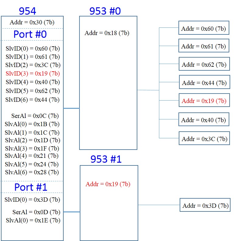
I have a DS90UB954 connected remotely to a pcb with two DS90UB953.

There are two possible I2C addresses for the 953 – 0x18, 0x19.

RX Port 0 is connected to 0x18 and RX Port 1 is connected to 0x19.

There is an accelerometer on the pcb also has the same two possible address 0x18 and 0x19.

I have selected 0x19 and connected it to the 953 (0x18) on RX Port 0.

I am using aliased addressing. BCC_CONFIG REG 0x58 is set to 0x5D

On most occasions I can correctly read the accelerometer ID register (0x33) without any problem.

However, sometimes the device powers up in such a way that the value returned is (0x00)

I scope both the 954 I2C bus and the 953 I2C bus. The correct data is output by the accelerometer (0x33) but it isn’t transferred correctly to the 954 I2C where it appears as (0x00)

I am wondering if there is some problem with the addresses being so close in value.  I can't see why this should be but this is the only device which ever causes an issue.

The transaction always appears on the 953 I2C bus which implies that it is being recognised as external to the 953 - at least in the Maser -> Slave direction.

Any help would be much appreciated.

Thanks

Paul

  • Hello Paul,

    Can you help us understand a little bit more about the order of events? Which devices power up in what order? Also what mode is being used for the 953/954? Synchronous?

    Best Regards,

    Casey 

  • Hello Paul,

    Any feedback?

    Thanks,

    Casey 

  • Hi Casey,

    Our power-up sequence is firstly 954 on the local board followed by the remote 953 - powered across the cable by a supply generated on the 954 pcb.

    Our operational mode is CSI synchronous.

    This occurrence of this issue is so infrequent that I can't be exactly sure of sequence with regards to connecting USB, power to USB2ANY, PoE to 954 pcb.

    Is this a known issue?  And if so, is it related to power sequencing?

    Please let me know if you require any more information.

    Thanks

    Paul

  • Hey Paul,

    There is no known issue persay but please pay careful attention to the power up sequencing of each part to ensure it meets the datasheet requirements. Failure to meet rail order/PDB sequencing can cause some strange issues on rare occasions. I have seen similar symptoms when the PoC voltage has a glitch which causes the power rails going to the serializer to glitch and come back up in the wrong order for example. Also see our video here on power rail sequencing for more information: https://training.ti.com/power-sequencing-fpd-link-devices?cu=1134310

    Best Regards,

    Casey 

  • Hi Casey,

    Thanks for the prompt reply.  I watched the video

    The 954 uses external 1v8 and the internal 1v1 LDO.  The PDB pin has 10k,10uF connected to 1v8 to hold in reset while the power comes up.

    The 953 uses external 1v8 only.  The PDB pin has 10k,10uF connected to 1v8 to hold in reset while the power comes up.

    They would appear to meet all the power-up requirements.

    The issue I'm seeing seems to be determined at power-up - once in the state only a repower appears to correct it.

    Do you have any thoughts as to whether the issue is likely to be in the 953 or the 954?

    Would a hard reset be likely to correct the issue? I haven't seen it often enough to be able to test.

    Is it permissible to have the PDB pin high at power up and then to issue a hard reset (driving a low pulse on the PDB pin) before using the device.  Or is it strictly necessary to meet the power-up conditions for PDB?

    Thanks

    Paul 

  • Hi Paul,

    Can't say right now where the issue exists. The hard reset is not required, it is explaining how long you should wait before applying the hard reset on the PDB. Although, do you get better results when you do a hard reset? 

    - Just to clarify, this issues is occurring rarely? or is it consistent?

    - Have you tried to provide a different address alias to the SER and DES? If so, what were the results?

    - Also, I was reading through the post and you mentioned 0x33? for clarification, is this the data you were expecting out of the accelerometer? or is this another address?

    - I noticed you are running the Back Channel at 25Mbps? Is that intentional? We recommend running at 50Mbps as the default setting for 953/954 sync mode, so BCC_CONFIG = 0x5E

    Regards,
    Mandeep Singh

  • Hi Paul,

    Do you have any other questions regarding this post?

    Regards,
    Mandeep Singh

  • Hi Mandeep,

    Apologies for being slow to get back.  To answer your previous questions.

    I have only seen the issue on 2 occasions.

    Both times a repowering was used to clear it - I didn't do a hard reset.

    The DES doesn't use an alias Address (does it?)

    The ALP profile seems to force the Alias for the two SER at 0x0C and 0x0D.(7 bit)

    So I haven't tried any alternative addresses.

    The 0x33 is the data that is output by the accelerometer to the 953 I2C (observed on the oscilloscope).  This is not transferred successfully to the 954 I2C. On that bus I observe 0x00.

    We sending the video data across a long twisted.  Required bandwidth is less than 2G, so reach is extended by running the back channel at 25M rather than 50M.  Are we correct in understanding that the forward channel rate is directly controlled by the back channel rate.

    My follow up questions:

    Is it recognised that closely related addresses can cause a problem?  I think I might have read that on one occasion but can't find the reference now.

    The fact that the problem has only been seen with a slave address (0x19) which matches the address of the 2nd 953 (although it  is actually connected to the 1st 953 with a 0x18 address) does lend weight to the possibility.

    I presume there is no issue with operating at a back channel rate of 25M.  Or is there? The device allow the rate to be configured.  What problem could result in not running at 50M?

    Thanks

    Paul

  • Hi Paul,

    Per i2c protocol, the LSB is a reserved bit and is used as an indicator for a read or write. Perhaps this explains why you are getting issues when you use the device ID 0x19. See

    2) There's no issues if you use 50MHz or 25MHz but your understanding is right. In Sync mode, the back channel will directly effect the Forward channel rate.

  • Hi Mandeep,

    Do you mean that the R/W bit can somehow cause confusion with addresses?  As the article you linked highlights the R/W bit does not form part of the address.

    It isn't obvious to me how the confusion can occur if the protocol is fully implemented.  I've attached a summary of the I2C connectivity in my current development.

    Devices using the problem address 0x19 are highlighted.  Can you please review and let me know specifically if and why the device address 0x19 is problematic?

    The fact that the problem occurs infrequently and appears to depend on powerup would seem to indicate that the dual use of 0x19 should not be a problem.

    Unfortunately, I have no simple way of changing the addresses of either device using this address.

    Thanks

    Paul


  • Hi Paul,

    I agree, the address is 7 bit, so the LSB is not effected if the addr is set to 0x19. In the overall diagram you shared, I don't see how the i2c address can be an issue. The alias for the sensor is 0x1f, so 0x19 is not used from the 954 standpoint as an address to communicate to the sensor. Rather the 953 on Rx0 will use it to communicate to that particular part. Also, the addresses are port specific, which further eliminates that this would be an i2c issue.

    The issue is intermittent during power-up. I would ask if you can repeat the test and check all the registers on the 953 and 954 to ensure you are not getting any errors or something odd because of the power up. Is it possible for you to repeat this and capture a reg dump? Perhaps it'll indicate something that could point us in the right direction.

    I haven't revisited our earlier conversations, so just to double check. The power-up sequence is following what we have in the datasheets? I would encourage that if you can monitor the power-up when this issue happens and ensure that all the rails are still in accordance and PDB as well. Also, when you see this issue, what is the voltage at the MODE pin and IDX pins? Is that still okay? Also, what is the part number of the accelerometer you are using? And how is this configured with the 953?

    Regards,

    Mandeep Singh

  • Hi Paul,

    I'm following up to see if you had any further questions regarding this post?

    Regards,
    Mandeep Singh