This thread has been locked.

If you have a related question, please click the "Ask a related question" button in the top right corner. The newly created question will be automatically linked to this question.

TPS65988: PU calculation

Part Number: TPS65988
Other Parts Discussed in Thread: TPD6S300A

Hi ,

The application i am working will be using 5V and 1.5A.

TPS65988 has internal current Source  referred the table 6.8 for the datasheet For 1.5A.

Can you help me find the Pull up values and pull down value for same 

  • Hi Manish,

    These pull-up/down values are internal to the TPS65988 and cannot be modified. The TPS65988 will determine the correct current advertisement based on the device attached on the Type-C port. The connected device will have a specific resistance on the CC line, either an Rd or Rp depending on if it is a source or a sink and the TPS65988 will read this resistance value and configure itself appropriately. I would suggest reading the USB Type-C specification for more details. This can be found on the USB-IF website.

    Thank you,
    Eric

  • Hi Eric,

    Thanks for the quick reply,

    below the table I have fetched from data sheet which will give me the PU and PD value this will help me to finalize the series resistor for intrinsic safety.  

    IH_CC_1P5 Source Current through each C_CC pin when in a disconnected state when Configured as a Source advertising 1.5A to a UFP 0.000166 0.00018 0.0001944 μA
    VH_CCD_1P5 Voltage Threshold for detecting a Sink attach
    when configured as a Source and advertising
    1.5A source capability
    1.5 1.55 1.65 V
    RP Calculated resistance value 9057.971 8611.111 8487.6543 ohm
    RD Pulldown resistance through each C_CC pin
    when in a disconnect state and configured as a
    Sink. LDO_3V3 powered.
    5.1 Kohm
  • Hi Manisha,

    These resistors are all internal to the TPS65988. There is no need to make any adjustments for these values. I would suggest referencing the TPS65988EVM for a schematic reference.

    Thank you,
    Eric

  • Hi Eric,

    I Understand that there are internal resistance,(The internal current source). I wanted to calculate the series resistor for CC pins so I just wanted to confirm the way is calculate the resistance value is correct. because on these resistance value the series resistor will be selected

  • Hi Manisha,

    I'm not sure I understand your question. There is no need to calculate any values for external resistances on the CC pins. When you connect a device to the Type-C port, it will automatically handle the negotiation and calculation of the resistance on the CC line. There is no need to calculate any resistance values on those pins.

    Thank you,
    Eric

  • Hi Eric,

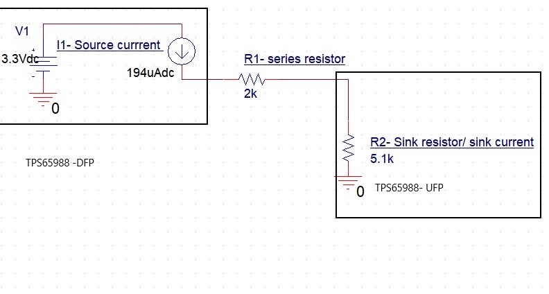
    let me rephrase the question we are connecting the 2K resistor on CC1 lines

    TPS65988 is used as  a DFP after that we have 2K resistor an at end we have  TPS65988 is used as  a UFP.

    In this cases will be there any voltage impact on UFP side?

  • Hi Manisha,

    Yes, this will have a negative impact on the TPS65988. There is not supposed to be any external resistance on the CC lines in your system. The TPS65988 that you have as DFP will automatically configure the internal pull-up resistor (Rp). Similarly, the TPS65988 that you have configured as UFP will automatically configure its internal pull-down resistor (Rd).

    Thank you,
    Eric

  • Correct "The TPS65988 that you have as DFP will automatically configure the internal pull-up resistor (Rp). Similarly, the TPS65988 that you have configured as UFP will automatically configure its internal pull-down resistor (Rd)."

    But in our application we have to connect a 2K resistor externally in series for safety purpose so I just wanted to know what will be the negative impact in that case

    Or what will the performance of IC

    As per my understanding the Current source internal to IC should take care if we connect the resistor in series externally

    Let me know if my understanding is correc

  • Hi Manisha,

    This will interfere with the accuracy of the TPS65988 cable detection and will cause errors. If you have a safety concern, I would suggest looking at the TPD6S300A device. It offers full USB Type-C protection and should be used instead of a series resistor on CC.

    Thank you,
    Eric

  • Hi Eric,

    The purpose of series resistor to controller power from intrinsic safety point of we in our application we don't have any requirement form ESD of High surge pulses.

    I have one more question regarding

    In this we will be using STM32F3 Microcontroller and we will be interfacing with I2C the PD controller.

    What will be the flow for selecting device as host or peripheral.

    Do you have and App note to understand this

  • Hi Manisha,

    By default, the TPS65988 will be the I2C Slave. You can refer to the Host Interface TRM document to see the register settings of the TPS65988: http://www.ti.com/lit/ug/slvubh2b/slvubh2b.pdf

    Thank you,
    Eric

  • Hi Eric,

    Thanks for clearing that by default it will be slave.

    Can you help me in understanding the high level flow for changing from Slave to master

  • Hi Manisha,

    If you are referring to I2C Slave/Master control on the TPS65988, it will be a slave by default and can be made an I2C master by enabling the I2C Master configuration bit in the Host Interface. The Host Interface TRM document that I linked in my previous post has this bit defined along with all the other configuration bits in the TPS65988.

    Thank you,
    Eric

  • Referring to above block diagram microcontroller will be the master and TPS65988 will be slave so the CC pins will be in DFP.(USB as host)

    And when microcontroller will be slave it will make TPS65988 as master so CC pins will be UFP (USB peripheral)

    Microcontroller

    TPS65988

    USB configuration

    Master

    Slave(by default)

    CC pin- USB as host

    Slave

    Master

    CC pin- USB as peripheral

    Let me know is this my understanding correct

  • Hi Manisha,

    The Type-C data role (DFP/UFP) has no relation to the I2C Slave/Master role of the TPS65988 and microcontroller. The Microcontroller will always be the master in your application as it will be sending messages to the TPS65988 and reading the register information on TPS65988. The microcontroller can send commands to the TPS65988 as the I2C Master to make the USB Data Role (DFP/UFP) change. This has no effect on the I2C role of the TPS65988. 

    USB Data role and I2C Master/Slave role are completely independent of one another.

    Thank you,
    Eric

  • Hi Eric,

    Thanks for the quick reply.

    As in USB OTG there is an ID pin which will define your device will be host or peripheral(Mini A and MIni  type connector )

    With that thought I was not able to understand who the TPS65988 will change from host to peripheral.

    Or is that the DR_SWP command will swap the data role from DFP to UFP

    Thanks

    Manisha Rajnale,

    Eaton Pune

  • Hi Manisha,

    The TPS65988 does not have a USB OTG pin. You can control the data-role through the DR_Swap commands and the Power Role through the PR_Swap commands.

    Thank you,
    Eric

  • Hi Eric,

    Can you help to more understand about the interfere with the accuracy of the TPS65988 cable detection and will cause errors.

    So  will there any impact on data transfer or what will be the error code

  • Hi Manisha,

    Adding series resistance to the CC lines will disrupt the accuracy of the PD negotiation and Rd/Rp detection of the TPS65988. If protection is needed, please use the TPD6S300A instead.

    Thank you,
    Eric