This thread has been locked.

If you have a related question, please click the "Ask a related question" button in the top right corner. The newly created question will be automatically linked to this question.

HD3SS3220: TUSB8041A Hub with HD3SS3220 MUX only connecting on USB 2.0 speeds

Part Number: HD3SS3220
Other Parts Discussed in Thread: TUSB8041A,

Hi,

To get a device that only needs a single USB cable, I have designed a board that will connect a camera and a microcontroller via the TUSB8041A hub. The connection to the PC is a USB type C plug that can connect to a PC with USB 2.0 / 3.0 / 3.1. This is my first take on a board with highspeed signals so the tracks are matched for length, but not impedance. The board kind of works, but only if I use a specific type and orientation of cables?

Here are the issues I'm having:

1. A USB 3.1 cable will not power the board, but both USB 3.0 and 2.0 will work.

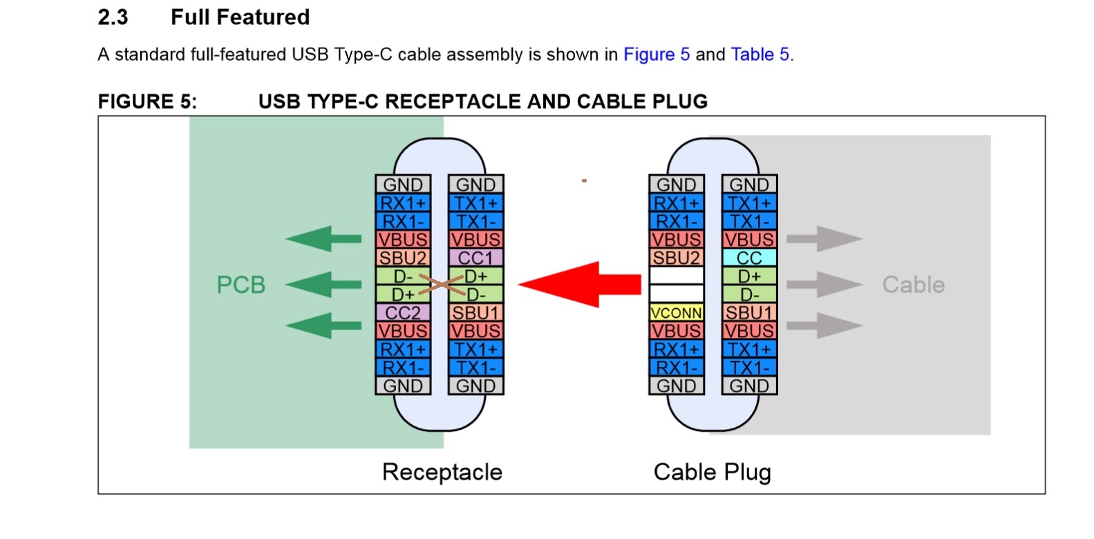
2. My Mac will only recognise the Hub if the Type C cable to the Mac is rotated in a specific orientation. I presume this is since only one side of the DP/DN pair is connected at the Type C connector? (A7 + A6 connected, B7 + B6 not connected)

3. The board only connects to my Mac as a USB 2.0 device. It will not get a superspeed connection.

With the HD3SS3220 mux, USB Type C cables are supposed to work both ways and any Type C cable should power the board. I've used Application notes as well as resources here on the forum when designing the board, but I must have missed out on something important here? I'm uploading the schematics in hope that someone can point me in the right direction. Thanks!

HubClicker.pdf

  • can you draw block diagram for different cases?

  • Jens

    A1, B1, A12, B12 of the Type C connector are GND, do you have all of them tied to GND?

    A4, B4, A9, and B9 are Type C VBUS, do you have all of them tied to VBUS?

    DP and DM must be shorted at the Type C connector to support both normal and flip orientation.

    What is the impedance of the SuperSpeed TX and RX?

    What is the DC voltage on CC1/2 for both normal and flip orientation?

    Thanks

    David

  • Not entirely sure what you meant here, but here is a block diagram of the board.

  • Hi,

    Thanks for responding! Not all connectors are shown in the Schematic symbol, but yes:

    - A1, B1, A12, B12 are tied to GND

    - A4, B4, A9, and B9 are tied to Type C VBUS

    - I'm quite certain that DP & DM should not be "shorted", but I guess you meant that they should be swapped+connected, right? ;-)

    - Regarding impedance -> it's not controlled in any way. I was under the impression that as long as the tracks were matched for length, it should work (though not well). I have since understood that the pairs need to be both matched and controlled.

    - Measuring CC1/CC2 with a USB 3.0 cable connection shows 1.3V on CC1 and 0V on CC2. Rotating the USB C connector swaps the two. Using a USB 3.1 cable does not power VBUS at all, but CC1 shows something quite interesting! I don't have an Oscilloscope at the moment, but CC1 cycles from 0.9V to 1.8V with this cable? CC2 is 0V. If I rotate the cable, this swaps the pins.

  • Jens

    Please refer to Figure 12 of the HD3SS3220 datasheet, DP and DM need to be shorted to support both normal and flip orientation.

    For the cable that does not provide the VBUS, you are probably using a e-marker cable. With a e-marker cable, power is provided through VCONN, not through VBUS.

    Can you please probe TX and RX on both side of the HD3SS3220 and see if you see both the host and hub are sending the LFPS? Typically the LFPS is a 20MHz clock signal with minimum amplitude of 800mV and maximum amplitude of 1.2V.

    Thanks

    David

  • Hi David,

    Regarding DP & DM, I don't understand. There is no mention of picture of these being shorted in the datasheet? It shows them being crossed at the output, but there is no termination (or short) to ground  in the datasheet. DM is connected to A6 & B6 and DP is connected to A7 and B7 on the USB Type C side and they connect directly to DM & DP on the hub.

    Regarding the 3.1 cable - if I understand correctly, I'll have to add a USB VBUS Switch to support this cable?

    I've done probing. On TXn I see this steady signal: 

    On TX1p I can see bursts of signals every 2(ish?) seconds that look like this: 

    Looking closer at these signals, they're not displaying anything sensible on my scope (Rigol DS1102E 100Mhz 1GSa/s):

    ... but it might be that the scope isn't fast enough to pick it up? There is no signals on TX2p or any of the RX channels.

    If I swap the cable around, things look quite different. TX1p is a steady +2.3V, TX2P is connected to GND and on TXp I can see this steady train of pulses: 

    So, it looks to me that the Hub tries to talk to the MUX, but nothing really gets past it?

  • Hi again David,

    I've been trying to find resources on shorting DP & DM. I can't find any mention of this, but I see a lot of mentions of terminating the USB 2.0 pairs to compensate for the impedance of the tracks. This typically involved a resistor across the pair, but could also be a more extensive solution. Is this what you mean by shorting?

    Thanks!

    J

  • for type-C cable, only has D+/D- on one side. In order to make cable work on both sides, you have to short D+ to D+ and D- to D- on Type-C receptacle.

  • Thanks for replying Brian,

    As a non-native English speaker, the word "short" typically means connecting something to ground or another net. I can see in the originally mentioned Figure 12 of the HD3SS3220 as well as the illustration above that the wires are crossing. I fully understand that the D+/D- signals must be on both sides of the connector in opposite order for the cable to work in both orientations. I also know I had this wrong in my schematic/board - thus it would only work as a USB 2.0 hub when the cable was in one orientation.

    What I do not understand here is the word "short" since I cannot see any "short" (as I know it) in the 2.3 illustration above.

  • I really need to send the board to Fab soon. Do you think that you could have a quick look at the measurements I did ?

  • waveforms didn't look like normal LFPS signal.

  • Right... The second version should be on its way in a few days with tuned tracks. I'll try again on this board then.

  • ok, We are waiting for test result from second version.

  • The new board works flawlessly. The main difference is D+/D- being properly connected at the receptacle as well as impedance controlled matched pairs for all data lines. Thanks for helping out guys!