This thread has been locked.

If you have a related question, please click the "Ask a related question" button in the top right corner. The newly created question will be automatically linked to this question.

MAX3221E: MAX3221E Functionality Problem

Part Number: MAX3221E
Other Parts Discussed in Thread: TRS3122E, TRS3253E,

Dear,Sir

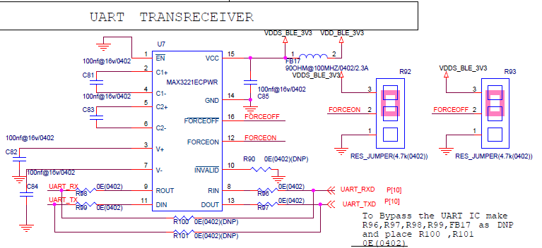
I am working on a project where we have implemented the MAX3221ECPWR IC ,In our application  we are communicating with the LCD Interface which Has the same Type of the IC built in it.

But before communicating with the IC implemented in the LCD ,We are doing a manual  testing for detection purpose.

My query is mentioned Below:

1)I am unable to detect the IC.We are operating the IC on the 3.3V of supply.

I have disabled the auto shutdown function and connected the force pins with the 3.3 V as displayed in the attached Image.

2)I am unable to generate the Voltage on the 2-4 And 5-6 Pins.

Voltage on 5-6 pins is 1.12V and on 2-4 pins is 0.78v.

What should be the voltage across the 2-4 and 5-6 Pins.?

3)I have connected the usb to UART Dongle and providing the input on the 9-11 Pin ,Still shorting the 8-13 Pin to see whether we are receiving the transmitted data displayed on the dock light.

Still we are unable to receive the transmitted data...!!

Please have a look on the below attached image of the schematic.

Please help on this query your help would be highly appreciated...!!

  • Hi Tirthal,

    I think your setup is correct for normal operation (FORCEON=FORCEOFF bar=H, EN bar=L). How did you measure the C1 and C1 voltage? If the device is powered on, it might be easier to check V+/V-. V+ should stay around 5.5V and V- around -5.5V. You can refer to this article for the V+ waveforms.

    e2e.ti.com/.../how-the-rs-232-transceiver-s-regulated-charge-pump-circuitry-works

    If V+ and V- look good, that means the charge pump works. You can send TTL logic (from MCU) to DIN and expect RS-232 signaling from DOUT. On the other hand, RIN takes RS-232 signal and converts them to TTL output by ROUT.

    Please let me know if it makes sense to you. Let me know if you have more questions.

    Regards,

    Hao

  • Dear,Sir

    Thanks for the response,Some minor shorting were found in our setup in which by mistake the dout pin was shorted with the 3.3v Pin.

    The voltage i am getting after fixing the setup are mentioned below :

    1)Pin 3 - V+ = 4.85 V

    2)Pin 7 - V- = -4.95 V

    3)Pin 2 - 4 - C+ / -C-  = 2.4 V

    3)Pin 5 - 6 - C+ / -C-  = 4.96 V

    4)Invalid = High = 3.3 V

    When i am manually providing the input on the Din Pin 11 (3.3v), the Dout Pin 13 is showing (-4.9 V).And  Din Pin 11 (GND =0 V ), the Dout Pin 13 is showing (4.9 V).

    I tried to communicate withe rs232 to UART Dongle and provided some input on the Pin 9-11 i received the output from the Pin 8-13,So i think the IC is functioning properly.

    Please suggest any other thing while dealing with the level shifter IC,If any.That would Help Us. 

  • Tirthal,

    The measurement results look good to me. The only note is that voltage of C1 and C2 pins toggle during charging cycle. The DC value may not mean much.

    What kind of level shifter do you need? If you want to interface with 1.8V logic, TRS3122E or TRS3253E can be considered.

    Regards,

    Hao

  • Dear.Hao L

    I would like to ask you one more question that ,what is the purpose of the Invalid Pin,As per the datasheet it s[specifies that it is a logic line. correct ?So it doesn't need to be powered correct..?

    In our Schematic if you see we have kept the invalid pin as Unconnected.

    In our setup in which we are performing the testing when i keep the invalid pin high 3.3v i am able to receive the output.

    But if i keep the invalid pin as unconnected then i am unable to establish the communication.Can you please specify whats the reason behind that.

    The LCD Which we are communicating is having the same IC MAX3221E implemented in it which have logic levels of -5.5 v and +5.5 v.

    Please help  on the above mentioned Query..!!

  • Tirthal,

    Please refer to section 8.3.4 of datasheet for the invalid function. The invalid bar pin is an output, which can be left open. If the communication fails, you could use the invalid bar pin for debugging. To be more specific, if the pin is L, that means something wrong with RIN pin (no RS-232 signaling detected). Can you elaborate what you mean 'unable to establish the communication'? Do you see the error in software or do you find there is no signal on the bus?

    Regards,

    Hao

  • Dear,Sir

    Apologize for the delayed response...!!

    I rebuild the whole setup and was working fine,So i think problem was in the setup the was custom made.

    Regarding the invalid pin it is showing the logic levels of 3.3 V and 0 V depending on the valid input on the Rin Pin of the IC.

    Have a nice Day..!!

  • Hi Tirthal,

    Thanks for the update!  We're glad to hear that the issue has been resolved.

    Regards,
    Max