This thread has been locked.

If you have a related question, please click the "Ask a related question" button in the top right corner. The newly created question will be automatically linked to this question.

TCAN1042-Q1: Protection Features

Part Number: TCAN1042-Q1
Other Parts Discussed in Thread: TCAN1043-Q1, TCAN1043

Hi Team,

Can you please clarify if the TCAN1042-Q1 can protect against CANH/L or CANL/Vcc or CANL/Vcc short?

Also, do the TCAN1042-Q1 and TCAN1043-Q1 both offer the same bus-level protection in terms of physical layer faults?

Thanks,
Mitchell

  • Mitchell,

    The device will not be damaged by the shorting conditions you mentioned as long as the absolute maximum pin voltage rating is not exceeded, but communication may not function. CAN communication is generally possible with CANH shorted to a supply voltage or with CANL shorted to ground.

    Yes, TCAN1043 and TCAN1042 will have the same fault tolerances. A notable difference, though, is that the TCAN1043 is able to report the presence of a fault via a dedicated output pin.

    Regards,

    Max

  • Hi Max,

    Thanks for the help here. Do we any measured waveforms to validate CAN bus line faults, handled by the TCAN1043? My customer is requesting this kind of data to build confidence that this is a fault protected PHY.

    Thanks,
    Mitchell

  • Mitchell,

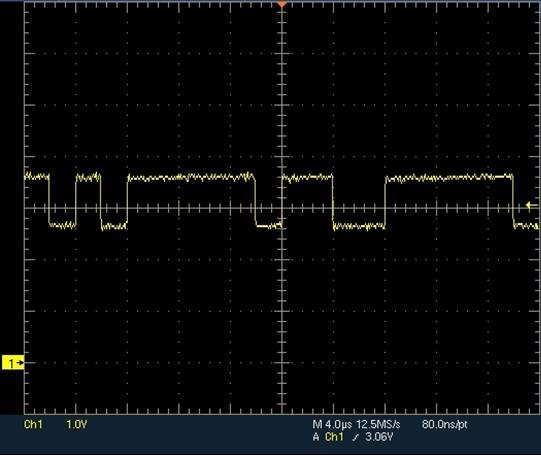
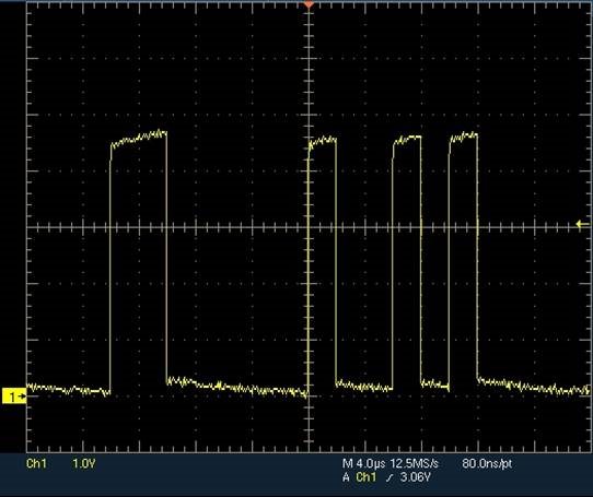
    Here's an example of what happens when CANL is shorted to GND on a bus operatin at 500 kbps.  Under normal circumstances (no shorts), the CANH line may look like this:

    The corresponding RXD output is:

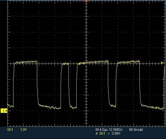
    Now, if CANL is shorted, CANH looks like this:

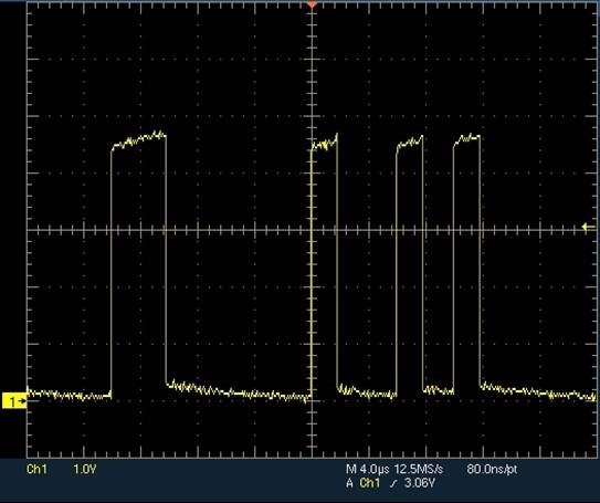
    Note how the CANH line still pulls up in the dominant state and creates a suitable differential output level.  This is because the output driver is designed to support up to 100 mA output.  In the recessive state, though, the output is not driven and the termination resistance causes the CANH voltage to pull to CANL (which is forced to ground).  This results in a differential level close to 0 V (the same as in normal operation, just at a different absolute level).  So, the RXD output remains the same:

    Note here that there are some PHYs specified as "low speed / fault tolerant" which are compliant to ISO 11898-3.  This typically requires a totally different PHY, though, and so I wanted to mention it in case there were any confusion.

    Max

  • Hi Max,

    Thanks for this! This is extremely helpful.

    Do you happen to have waveforms recorded for CANH shorting directly to CANL as well? It will be good to share the scope shot where you can capture normal operations to bus faults showing the differential voltage went from a CAN pulses to 0V (for CANH-L) or 2.5V for CANL-ground or CANH-ground.

    Thanks,
    Mitchell

  • Hi Mitchell,

    Unfortunately I don't, and because of some weather-related issues with our lab at the moment I'm not able to capture these (the other waveforms I had on hand already).  I can tell you that if CANH is shorted to CANL, the differential voltage between them will be 0 V and the receiver will only report a recessive state on the bus.

    If you think through the different possible shorting scenarios, you can predict the device behavior based on its performance as documented in the datasheet.  Understanding the behavior of the device in this way is better in my opinion that trusting in the results of a single measurement (with its assumptions related to battery voltages, other nodes on the bus, shorting impedances, etc.).  I've put together a document that describes how a transceiver would behave under different system-level fault conditions.  I will send it to you via e-mail, and hopefully that can be used to give some better confidence in the part.

    Regards,
    Max