This thread has been locked.

If you have a related question, please click the "Ask a related question" button in the top right corner. The newly created question will be automatically linked to this question.

DS90UB953-Q1: connect DS90UB962-Q1 issue

Part Number: DS90UB953-Q1
Other Parts Discussed in Thread: DS90UB962-Q1, , DS90UB933-Q1

Hi Sir,

Need help to review the setting. There has issue in DS90UB953 connect to DS90UB962.

Current information as below:

DS90UB962 i2c id: 0x60 (8bit)

Use “RX0” Channel

DS90UB962 CSI_output use 0

962 to 953 setting as below:

0x6D=0x78

0x10=0x00

0x4C=0x01

0x58=0x5E

0x32=0x01

0x33=0x01

DS90UB953 is using  yuv 8bit mipi 4Lane CMOS sensor

DS90UB953 I2C ID is 0x32(8bit)

Need 962 to 953 mipi 4Lane YUV “initial table”

Kindly help to provide suggestion, thanks.

Ja


  • Hi Ja,

    What is the issue you are having? Are you not getting video output? The register settings look okay, I've clarified them below for reference.

    0x6D=0x78 //CSI mode

    0x10=0x00 //GPIO0 settings

    0x4C=0x01 //Read_write port 0

    0x58=0x5E //50Mbps, sync.

    0x32=0x01 // Read write Port 0

    0x33=0x01 // Forwarding enabled

    What is the fps and resolution of your imager or what is the CSI rate that the imager is outputting?

    Also, what is the value of registers 0x04, 0x1f, 0x35, 0x4c, 0x4d, 0x4e, 0x58, 0x6d, 0x7d on the ds90UB962? Please read these registers twice because there's some Clear on read registers so we want to know which errors are recurring, so you can post both results in your response. For example, read these registers, wait about 10 secs, then read these registers again. Please post results from both times you read these registers in your response.

    Regards,
    Mandeep Singh

  • Hi Sir,

    We are working on the DS90UB953-Q1 connect DS90UB962-Q1, but we still fail to see the image from CMOS image sensor. 

    Thus we are doing the following action.

    1. We test DS90UB933-Q1 connect to DS90UB962-Q1. Is it OK to see the CMOS sensor image by platform. => It seem we could make sure 962 function is OK when we use DS90UB933-Q1

    2. The following register is for your information. 

    962 --- Register
    0x04=0xd0
    0x1F=0x00
    0x35=0x01
    0x4C=0x01
    0x4d=0x13
    0x4e=0x6D
    0x58=0x5e
    0x6d=0x78
    0x7d=0x00

    3. We measure the 953+962 and 962 MIPI output as attached photo.

    4. We find the FS difference comparing to use 933 vs 953.

    a. 933+962 => fs  is 390ns

    b. 953+962 => fs is 327ns

     Question:

    1. If the fs different to influence the image out put, how we adjust our setting to get the 953+962 image output.

    2. Could you provide the information whether 953+962 sucessfully use in the which platform.

    3. Any suggestion to make the 953+962 link successfully.

    Ja

    Thanks.

  • 1. We test DS90UB933-Q1 connect to DS90UB962-Q1. Is it OK to see the CMOS sensor image by platform. => It seem we could make sure 962 function is OK when we use DS90UB933-Q1.
    - What do you mean by OK to see the CMOS image by platform? Are you asking if the 933 and 962 are compatible or work together? Then yes, they are OK.

    2. The following register is for your information.

    962 --- Register
    0x04=0xd0 //
    0x1F=0x00 // 1.6G CSI TX speed
    0x35=0x01 // CSI data is available on CSI Tx port, Data is not synchronized
    0x4C=0x01 // Read/Write Port 0
    0x4d=0x13 // Port 0 has LOCK and PASS. Lock STS changed.
    0x4e=0x6D // Line Count changed, Freq stable, CSI error
    0x58=0x5e // BC speed is 50Mbps.
    0x6d=0x78 // CSI mode.
    0x7d=0x00 //

    3. We measure the 953+962 and 962 MIPI output as attached photo.
    - Is this the CLK or data? is it P or N? You can see section 8.2.3 in the DS90UB962-Q1 datasheet. Nevertheless, in the capture you shared I can see that the signal is going into the different LP modes and
    I notice a small section that looks like the High speed data. Furthermore, register 0x35=0x01 means that you have valid data at the CSI Tx port.

    4. We find the FS difference comparing to use 933 vs 953.

    a. 933+962 => fs  is 390ns

    b. 953+962 => fs is 327ns

    By FS, do you mean FrameStart? Are you doing Synchronized forwarding? We have registers such as 0x35[1] that indicate if the streams are synchronized. In your case, they are not.

     Question:

    1. If the fs different to influence the image out put, how we adjust our setting to get the 953+962 image output.
    - I'm assuming you are asking about synchronized forwarding. How are you generating your frame sync signal? Have you tried to

    2. Could you provide the information whether 953+962 successfully use in the which platform.
    - What do you mean platform? Like SoC? or Imager? Our customers use a wide variety of imagers and SoC. Anything that's MIPI DPHY Version 1.2 / CSI-2 Version 1.3 compliant will work.

    3. Any suggestion to make the 953+962 link successfully.
    - I'm a little confused because you are asking about 933 and 953. My assumption is Port 0 has 953 on it and my suggestion would be to first focus on one imager and make sure you can capture with one imager, then go to two. I noticed register 0x4e and 0x4d show lock change and errors on the CSI. Did you read this twice as I mentioned? If not, please read these registers twice and check if these errors are recurring. This should be the first step. Make sure you don't have errors here. Then, I noticed that you are getting valid CSI data at the CSI TX port 0x35[0], this indicates that there's some issue with capturing this data from the SoC side. If you are unsuccessful in capturing, I'd recommend turning on PatGen on the 954 and seeing if you can capture the data with PatGen enabled.

  • Hello,

    Do you have any further questions/updates in regards to this post?

    Regards,

    Mandeep Singh

  • Hi Sir,

    1. Current development DS90UB953 model is able to link DS90UB954. The Image seem to be fine. (Attached 1)

    2. 953 connect 962 has link issue.
      1. Due to we want to setting the Freq 50Mhz and expect to Pass, but we did not get pass result and fail to see the image.
      2. The freq setting is based on datasheet Page 101.
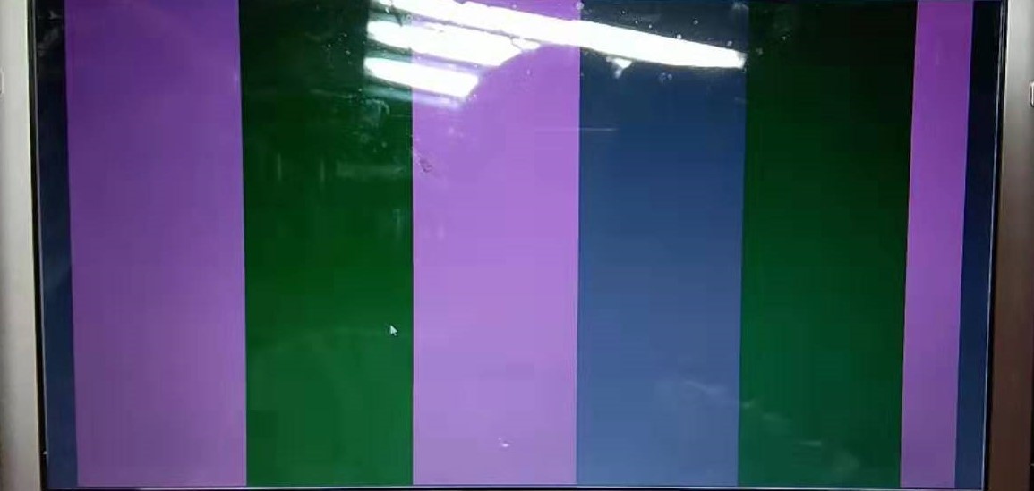
      3. If we set the the freq is 10Mhz, image quality is not correct (Attached 2)

    Kindly help to advise how about the correct setting when 953+962.

    Ja

  • Hi Ja,

    1) The back channel rate should be 50Mbps when linking to the 953. Have you tried this on different 953/962? Are you getting the same result on all of them?

    2) Try to enable PatGen on the 962 and confirm if you can capture this successfully.

    a) There's a code example in the 962 datasheet section 7.5.12.4.

    Regards,

    Mandeep Singh

  • Hi Mandeep,

    1. When 0x58 set 5E, 4D is not able to link. Due to current developed 953 module could connect 954, please kindly advise why 953 could not connect 962. Please kindly advise.

    2. Current testing result.

    Kindly give your comment and suggestion.

    Ja

  • Hi Ja,

    1) This should not be happening, Can you share a full reg dump of the 953 and 962 when this issue occurs? 

    2) This is good, this confirms that the 962 can communicate to the processor and you are able to capture the link. Now, Don't turn on PatGen on the 962, instead, turn on PatGen on the 953. There's an example of this in section 7.6.4 on the 953 datasheet. Please make sure you do this on the 953 and not the 962. Try to capture the results with 50Mbps Back channel and with 10Mbps and share the results.

    Regards,
    Mandeep Singh

  • Hi Mandeep,

    We attached 3 file for your information. 

    When the 962/58 change to 5E, could not lock. Please kindly noted.

    Attached 953reg is 962/58 = 5A information.

    Kindly help to check these file and let us know your suggestion.

    Ja

    1.

    /cfs-file/__key/communityserver-discussions-components-files/138/962reg_5F00_58H_5F00_5A.txt

    2.

    /cfs-file/__key/communityserver-discussions-components-files/138/962reg_5F00_58H_5F00_5E.txt

    3.

    /cfs-file/__key/communityserver-discussions-components-files/138/953reg.txt

  • Hi Ja,

    Can you also try the PatGen on the 953 and share those results as I mentioned in my last post.

    I just looked at the 953 registers. You're doing 2 lane configuration, is that intentional?

    Additionally, registers 0x5C and 0x5D on the 953 are showing errors. These are clear on read errors, can you read these registers, then wait about 10 seconds and read them again. I want to know if the errors are recurring in the use case when you're not able to capture data.

    Regards,
    Mandeep Singh

  • Hi Mandeep,

    The image sensor only use 2 lane. Do you have any comment?

    For the further data collecting, we will check and see whether we could update to you.

    Ja

  • Hi Mandeep,

    1. CMOS Sensor only use 2 lane.

    2. Please refer the following file for your suggestion and need your comment. Condition as below:

    The first read is  962REG,953REG_1,

    Then, setting 0X5C and 0X5D is "00",

    Read 953 as 953REG_CLR_2.TXT

    /cfs-file/__key/communityserver-discussions-components-files/138/962REG.txt

    /cfs-file/__key/communityserver-discussions-components-files/138/953REG_5F00_1.txt

    /cfs-file/__key/communityserver-discussions-components-files/138/953REG_5F00_CLR_5F00_2.txt

    Ja

  • Hi Ja,

    Just so we're clear, you read all the registers initially which is "953REG_5F00_1.txt" then you wait 10 seconds and then again read all the registers which is "953REG_5F00_CLR_5F00_2.txt" , is that correct understanding? and What do you mean by "Then, setting 0X5C and 0X5D is "00"?

    What I'm observing is that there's CSI errors coming into the 953, so there's a potential issue with your imager settings/configuration/set-up possibly. To further confirm this, can you please enable PATGEN on the DS90UB953 and capture the output on the CSI TX of the 954 and share the results? If this output is okay, then likely the issue exists on the imager side.

    Regards,
    Mandeep Singh

  • Hello Ja,

    Were you able to check the above information from Mandeep? Was the issue resolved?

    Best Regards,

    Casey 

  • Hi Casey,

    Thanks for asking. Our development DS90UB953 module can be work now, however, our developed DS90UB962 module could not link our DS90UB953 module. And we do not have clue how to fix this.

    Ja 

  • Hi Ja,

    I didn't get a response to my last post. If you still need help, can you provide a response?

    ----------------------------------------------------------------------------------------------------------------------------------------------------------------------------------------------------------------

    Just so we're clear, you read all the registers initially which is "953REG_5F00_1.txt" then you wait 10 seconds and then again read all the registers which is "953REG_5F00_CLR_5F00_2.txt" , is that correct understanding? and What do you mean by "Then, setting 0X5C and 0X5D is "00"?

    What I'm observing is that there's CSI errors coming into the 953, so there's a potential issue with your imager settings/configuration/set-up possibly. To further confirm this, can you please enable PATGEN on the DS90UB953 and capture the output on the CSI TX of the 954 and share the results? If this output is okay, then likely the issue exists on the imager side.

    Regards,
    Mandeep Singh

  • Hi Ja,

    I still haven gotten a response on that last post? Do you have any further question for us or this topic?

    Regards,
    Mandeep Singh

  • Hi Mandeep,

    Thanks for asking. Our developed DS90UB962-Q1 board could not link our DS90UB953-Q1 board now. When we have further testing result, I will update.

    Ja.