This thread has been locked.

If you have a related question, please click the "Ask a related question" button in the top right corner. The newly created question will be automatically linked to this question.

DS90UB914A-Q1: I2C communication is failing from Serializer

Part Number: DS90UB914A-Q1

Hi Experts,

Following is the block diagram for our project. In this, I have to communicate the SDF on Camera Head Sensor. For that, I have to configure Deserializer,Serializer and then I2C on the Camera Head sensor. 

For me, now communication is happening between Deserializer & Serializer. But after all configuration of both, I could not communicate with any of the remote slave device( EEPROM(ID-0x50), GPIO Expander(0x20), PMIC(0x28), I2C-SPI bridge(0x3D) inside the FPGA etc in this case). 

I am attaching the register settings for Deserializer and Serializer. Please let me know if any other things i have to consider. 

Thanks in Advance!

BR,
Sagar

  • Hello Sagar,

    Per the register settings, please double check the PMIC(0x28)'s setting at Reg[0x0A], it should be 0x50 (0x28<<1), and also 0x5A will be conflict with SER_ID.

    Same time, suggest you can check whether you can talk with slave device locally, and if the processor/IUC supports clock stretching?

    BTW, a related AN of 'I2C over 913/914 xx' as below for your reference.

    http://www.ti.com/lit/an/snla222/snla222.pdf

    Thanks & BRs,

    Cheney

  • Hi Cheney,

    Thanks for your reply.

    As per this settings 0x03[0] = 1 and 0x21[1] = 0, it will allow to communicate with remote slave device attached to serializer. These settings i have done correctly. But still I am not getting any respond from slave. You can see settings in the register configuration. 

    Per the register settings, please double check the PMIC(0x28)'s setting at Reg[0x0A], it should be 0x50 (0x28<<1), and also 0x5A will be conflict with SER_ID.


    -> Okay. There will be no communication for the PMIC but all other devices are correct right? Why there is no response from other devices.?

    One more doubt

    If PMIC ID is 0x28, then i will configure it as 0x50(0x28 << 1) in deserializer. But what should be the ID for remote device when i am calling for read or write? Is should be 0x28 or 0x50? Please clarify. 

    Please let me know if any additional setting there, that I am missing. 

    BR,
    Sagar

  • Hello Sagar,

    Yes the mode's setting is correct and no issue here, so this's why I suggest to check the 'clock stretching' & 'slave device local response' as next step, also more detail as below:

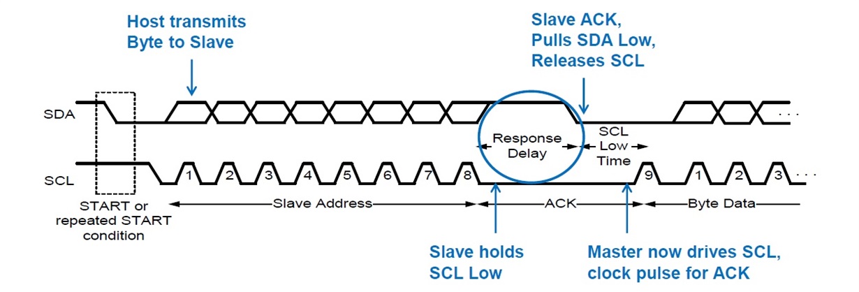
    • When I2C communicate with remote device through FPDLINK, the I2C host controller must support clock stretching as there's a 'response delay' like below:
    • Also better to double check whether the host on 'CPU box' can talk with slave devices at the 'camera head main PCB' locally.(bypass FPDLINK and connect the I2C of CPU/camera directly), it's helpful to isolate if any HW issue at the camera PCB.

    And for the actual physical I2C ID, it always be 7bits, we do the left shift at 914's register just because: the bit[0] at 914 related register is reversed or for other purpose.(default 0). 

    So for PMIC in your case, if the host also use 7bits I2C address, you should still use 0x28 as the ID for communication. but in case the host used other I2C address format, please do the transition accordingly.

    Thanks & BRs,

    Cheney

  • Hi Cheney,

    I tried with bypassing the FPD link but I could not get any response from any of the slave device. One of slave ID is 0x3D and master support the 7 bit address format. So what could be the address to the slave device while performing read or write operation in bypass mode? Is it 0x3D or something else?

    Please support on this.

    BR,

    Sagar

  • Hello Sagar,

    If bypass FPDLINK and do the I2C communication locally show no response, I think there're some issue at the HOST/salve devices' I2C design/compatibility, for example perhaps some HW issue of the slave devices, suggest you double check related device's datasheet and design guide for identification.

    Thanks & BRs,

    Cheney

  • Hi 
    I am able to communicate with slave device. Now the problem is that, after initializing ser and deser, PDB pin is going low if there is no activity on i2c bus. It should not be go low once it is HIGH. Also controller pin is not controlled by any other.

    What could be the reason? Please explain.

    BR,

    Sagar 

  • Hi Sagar,

    Yes, the 914/913 device will not pull PDB down itself,  does PDB just connect to VDDIO with a RC or connect and control by external processor? and does 913 or 914(or both)'s PDB pin will going low?

    Suggest you can monitor the VDDIO/PDB pin's voltage waveform first, and if the PDB pin be controlled by external processor, also suggest check its related output setup at the same time.

    Thanks & BRs,

    Cheney 

  • Hello Sagar,

    Was this issue resolved? As Cheney said, our devices have no ability to pull PDB low on their own. The pulldown must be coming from an external circuit to the device. 

    Best Regards,

    Casey 

  • Hi

    It has been solved.

    Thank you for your support