This thread has been locked.

If you have a related question, please click the "Ask a related question" button in the top right corner. The newly created question will be automatically linked to this question.

DP83867IR: CRC Errors on reverse loopback

Part Number: DP83867IR

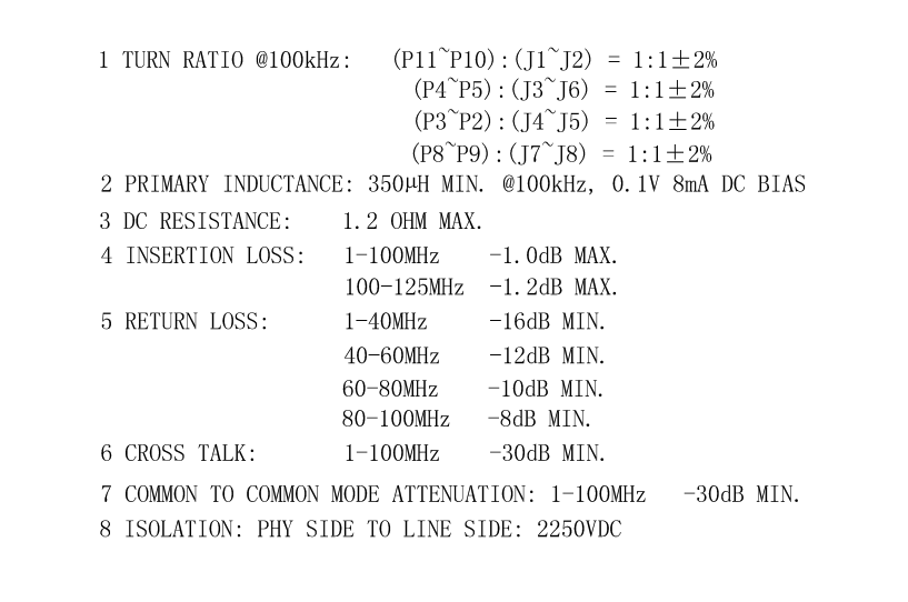
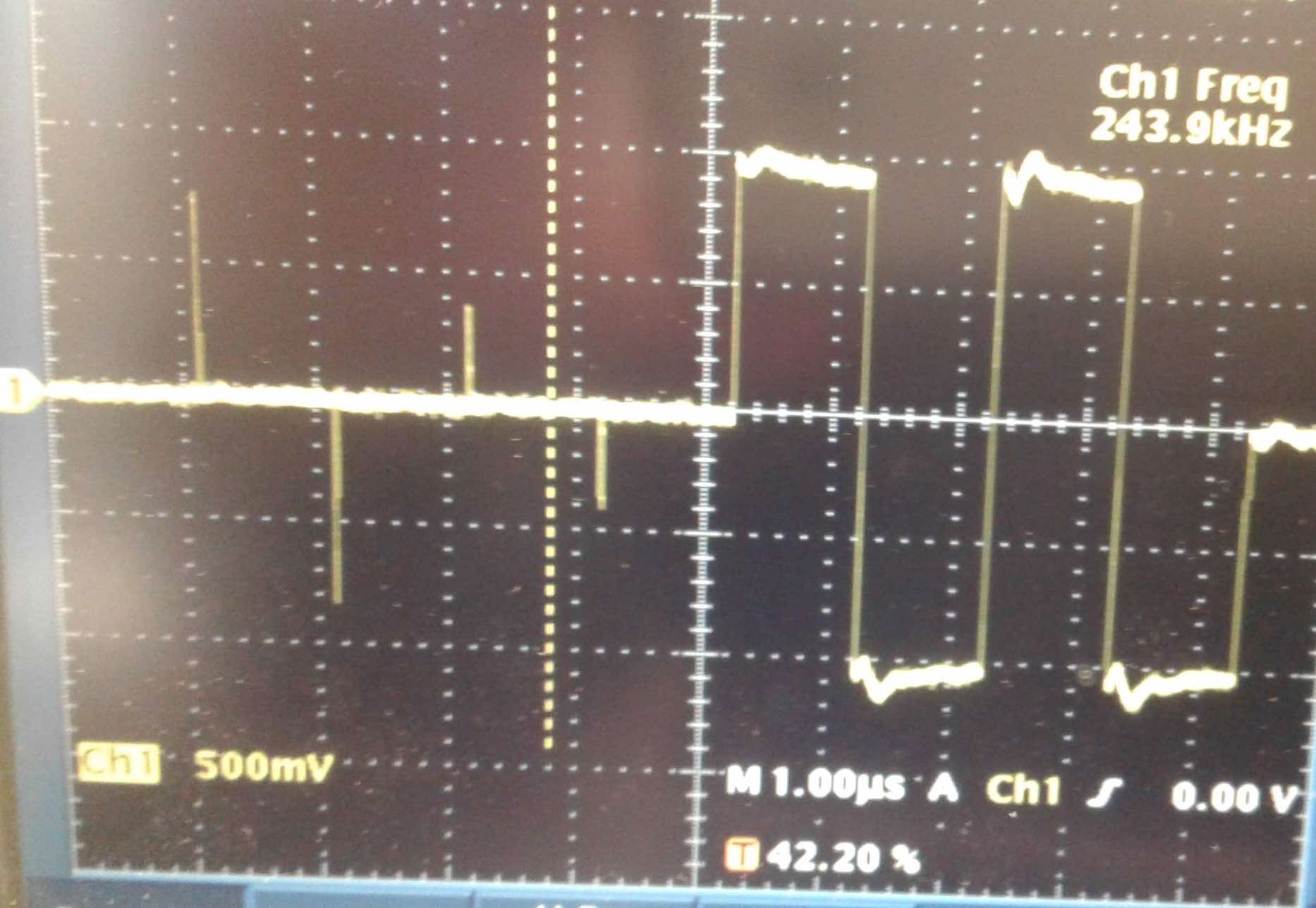
We have a board using the DP83867IRRGZT part.  We have a problem with CRC errors on the link.  It seems that the analog side is the problem.  With reverse loopback enabled, we get about 5% packet loss, and the computer interface says they are due to CRC errors.  We are using the TE integrated magnetics 6-2301994-1, which from what I can see meets all the requirements for the magnetics.  We designed the board with 100 ohm differential impedance, and we use TPD4E05U06DQAR TVS components on the data lines on the PHY side of the magnetics.

The link comes up and works normally apart from the packet loss.  I have gone through the troubleshooting guide, and I don't see anything in there that is a problem.

I would appreciate any ideas for getting this fixed.

Thanks!

  • Hello John,

    When you mention that the magnetics chosen meets all the requirements, what specifications have you compared?

    What is your clocking solution, are you using a crystal or an oscillator? What is the ppm error?

    Thanks,

    Vibhu

  • Hi.  I got the specs from AN-1469, the PHYTER design app note.  I didn't see any specs in the DP83867 data sheet.  Here's the specs from the TE data sheet.

    The clock is an oscillator, driven by the 1.8V rail.  The part is the Abracon AMPMGFB-25.0000T, +- 25 ppm stability.

  • Today I went through the IEEE Ethernet compliance testing for the 1000 Mb case.  I don't have a compliance tester, but I captured the waveforms for the various tests, and at least the waveforms look right.  I did the mode1 test by hand, and it seems like all 4 channels are the same, and I think they all pass the tests to the limit of my measurement ability.  All the channels look the same, with a bit of overshoot on the second half of the plot. 

  • Here's a picture of the layout of the PHY to MDI interface.

  • Hi John,

    Were you able to achieve a solution for this?

    If so can you drop me an email to bpadmanaban@aversan.com

  • I have some more information from testing today.

    We see zero errors running the loopback test from the MAC to the digital loopback point (Reg 0x0016 set to 0004).  If we extend our test to the analog loopback point setting register 0x0016 to 0008, we see a few errors creep in, about 2 or 3 every 65k packets.  Is this normal?  If not, what can cause it? 

    Also, we tested the 100 Mb and 10 Mb interfaces, and usning the reverse loopback we can send packets error-free from the host to the board and back with the 10 Mb interface.  We get a few errors on the 100 Mb interface, and many more errors on the gigabit interface.

    We are using an Intel EN5319QI Power SOC power supply for the chip's power supplies.  Is it OK to use these; or do we need linear supplies?  I notice that the eval board uses an LDO for the 2.5 and the 1.0 volt power supplies.

    Any ideas for us?

  • Hello John,

    Sorry for the delayed response. If this issue is still open, would you be able to do the same tests with the EVM and see if you see the same issues at 100M and gigabit?

    As long as the power supplies meet the requirements in the datasheet there shouldn't be an issue. Is there a way to use an external supply on the board, to see if that makes a difference?

    Thanks,

    Vibhu

  • Some info of my debugging in progress:

    1. In Analog Loopback you should have the 100E Terminated across 1Gbps Pairs to work successfully (i had to do this)

    2. Am running with the same issue as yours(Digital loopback works fine for me, Reverse and analog loopback gives trouble) - I have done this

    3.Also i checked if MAC received packets in reveres loopback failed condition and they didn't (So the Phy is not sending it through)-I have done this

    4. I would recommend to check the CLK_OUT pin to have it to decoded the receive clock from MDI when packets drop across  ->Am yet to do this

    5. Are using PRBS when doing Loopback or sending packets from MAC?(reason: we can check if PRBS is in sync if PRBS is used)->Am yet to do this

    6. Can you check in LEDCR1 if receive error or transmit error bit is set or if you can decode from RGMI side from RX_CTL and RX_CLK ->Am yet to do this

    7. Am not if it will impact  check 9.2.1.2 Clock In (XI) Recommendation of datasheet-> I have not followed this

  • Thanks for the input.  I will try some of these things.

    Some info of my debugging in progress

    1. In Analog Loopback you should have the 100E Terminated across 1Gbps Pairs to work successfully (i had to do this)

    Thanks for the idea.  I will try this.  I tried it with the cable unplugged, plugged in to a computer (very bad results), but I did not try it with a terminated cable. 

    2. Am running with the same issue as yours(Digital loopback works fine for me, Reverse and analog loopback gives trouble) - I have done this

    3.Also i checked if MAC received packets in reveres loopback failed condition and they didn't (So the Phy is not sending it through)-I have done this

    4. I would recommend to check the CLK_OUT pin to have it to decoded the receive clock from MDI when packets drop across  ->Am yet to do this

    This is OK

    5. Are using PRBS when doing Loopback or sending packets from MAC?(reason: we can check if PRBS is in sync if PRBS is used)->Am yet to do this

    I have nit tried this yet.  Will do so

    6. Can you check in LEDCR1 if receive error or transmit error bit is set or if you can decode from RGMI side from RX_CTL and RX_CLK ->Am yet to do this

    Also a good idea.  I will try it.

    7. Am not if it will impact  check 9.2.1.2 Clock In (XI) Recommendation of datasheet-> I have not followed this

    I have checked this.  My clock is well within spec.

  • I will try the tests on the EVM.

    I am going to try to power up the board with linear supplies and see if that helps.  The noise on the 1, 1.8, and 2.5 supplies are withing spec as far as the data sheet goes.

    Is our board layout reasonable as I showed it in a recent post?  We may try to respin the board with some different layouts to try to get a reliable link if you think we should look into that.  I don't seem many if any examples of gigabit ethernet with a magjack.  The TI EVM uses a discrete magnectics and connector. 

  • Hello John,

    Please let us know how the tests on the EVM go, could you please send me your schematic so I can double check the magnetics and MDI connections.

    Is our board layout reasonable as I showed it in a recent post? 

    If you are asking about the MDI lines pictured earlier in the post, can you confirm that you are following the instructions from "9.2.2.2.1 MDI Layout Guidelines" of the datasheet.

    Thanks,

    Vibhu

  • Hi Vibhu.

    Attached is the schematic.  The last page is the PHY chip and its friends.  The first 2 pages are where the PHY connects to the FPGA.

    On the board layout, we did attempt to follow all the guidelines.

    pgs3_4_5.pdf

    Vibhu Vanjari said:

    Hello John,

    Please let us know how the tests on the EVM go, could you please send me your schematic so I can double check the magnetics and MDI connections.

    Is our board layout reasonable as I showed it in a recent post? 

    If you are asking about the MDI lines pictured earlier in the post, can you confirm that you are following the instructions from "9.2.2.2.1 MDI Layout Guidelines" of the datasheet.

    Thanks,

    Vibhu

  • Hello John,

    Just following up, were you able to test on the EVM?

    "On the board layout, we did attempt to follow all the guidelines." Just wanted to clarify was there anything that you couldn't follow?

    I do not see any issues with the schematic. Are your supplies following the supply tolerance and clock following the ppm requirement?

    Is your RBIAS resistor 1%?

    Thanks,

    Vibhu

  • Vibhu Vanjari said:

    Hello John,

    Just following up, were you able to test on the EVM?

    "On the board layout, we did attempt to follow all the guidelines." Just wanted to clarify was there anything that you couldn't follow?

    I do not see any issues with the schematic. Are your supplies following the supply tolerance and clock following the ppm requirement?

    Is your RBIAS resistor 1%?

    Thanks,

    Vibhu

    Hi Vibhu.  I can't remember what the EVM test was going to tell us, but the analog loopback works OK with the RJ-45 terminated with a 100 ohm cable termination, but we still have errors at the host end of the wire.

    Our bias resistor is good.  Our power supplies are in spec.

    Since the PHY seems to work fine, we are suspicious of our PCB between the PHY and the integrated magnetics module.   We have a TVS part in there, the TPD4E05U06DQAR.  I noticed that the eval boards do not use any TVS parts.   Is the Phy robust enough on its own that we can eliminate the TVS part?

    Also, our trace lengths within the pairs are not very tightly controlled.  See the last column in the table below for the differences between legs in a pair.  Is it possible this is causing the trouble?

    Thanks for your help.

    John

  • Hello John,

    The MDI pins are rated for 8 kV (HBM), so we typically do not put extra ESD protection on our EVMs.

    Can you confirm that these values in the table above are in mils? They seem to be on the higher side but still seem to be ok. The trace length tolerance is hard to quantify as it is different board to board.

    Do the errors go away when you link at a lower speed?

    Based on the part# on your schematic looks like the ppm error on your oscillator looks good too.

    Are you continuously reading or writing to the MDIO/MDC while running these tests?

    Thanks,

    Vibhu

  • Hi Vibhu.

    Thanks for the information.

    Yes, these are in mils. 

    The errors still occur with 100 mb/s at about the same percentage of packets, but obviously at a lower rate per second.  10 megabit links up fine with no errors.

    We are not reading or writing the MDIO/MDC continuously.  I am only reading and writing with the usb-mdio demo program occasionally, and while I am not monitoring the link.

  • Hello John,

    Please read Receiver Error Counter Register (RECR) and see if it increments with more packer errors.

    I assume that you are sending data using the FPGA, for the loopback test, do you see the same issues when you use the PRBS generator?

    Thanks,

    Vibhu

  • Hi Vibhu.

    I will do some tests today and read the RECR.

    I am  sending data with the FPGA. 

    To recap where I am, I am now able to send data at full gigabit data rates (1344 byte packets) through the PHY to the digital loopback with no errors.  I can also send them through the PHY to the analog loopback with no errors if I terminate the RJ-45 with 100 ohm test cable that I use for probing the RJ-45 port.

    So now I am left with my host still receiving errors.  I am convinced now that my PCB is flawed in some way.  I did not have the differential traces to the magnetics matched in length (the intra-pair lengths were off by up to 60 mils), and I had no chassis ground or ground flood on top of my board.  I have redesigned the board, and will be sending it out for fab.  Attached is a screenshot of the interface.

    John

  • Hello John,

    Thanks for the summary, I will close this thread for now and once you have tested your new board, please create a new thread referencing this one and we can take it from there.

    Thanks,

    Vibhu

  • Hi Vibhu.

    I have fixed the problem.  It turned out to be simply the clock oscillator.  Even though it was specified to 25 ppm, it had a LOT of jitter.  I replaced it with a better (in terms of jitter) clock and all is well.  >>1 billion packets with no errors.  :)

    You should consider adding a jitter spec to the data sheet as well as a frequency stability spec.  Also, looking back at it, it makes more sense to use just a crystal and allow the PHY to generate the clock from that.  I will do that from now on in my designs.

    John