This thread has been locked.

If you have a related question, please click the "Ask a related question" button in the top right corner. The newly created question will be automatically linked to this question.

DP83867IR: DP83867IR

Part Number: DP83867IR

Hello,

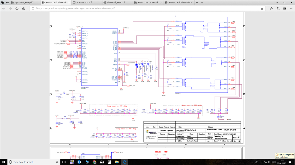
We have used DP83867IRRGZ  in our custom design board:

We are using Gigabit Ethernet switch with PC. When ever we connect single board to switch it was working fine but when we connect more than one i cannot ping the the other board. thing is when multiple boards  connected it can only ping single board and other board is getting ignored but link is established in both boards. what is the solution for which it  has to  work when multiple boards are connected to switch please suggest us ASAP

Regards

Sarath 

  • Hello Sarath,

    Can you please read these registers 0x0000, 0x0001, 0x0004, 0x0005, 0x0009, 0x000A, 0x0011 on both PHYs, compare the differences, and let me know what the differences are.

    Please also confirm the two PHYs are configured to different addresses.

    Thanks,

    Vibhu

  • Hello Vibhu,

    Please find the below list of register for two boards connected to switch(D-Link DGS-1008A),no difference found.But when we try to ping the card initial card is pining in no time but the next board is taking around 10 sec to ping.

    Please also confirm the two PHYs are configured to different addresses

    Yes, both are configured with different IP addresses.

    --------------------- IP Address 1.3 -----

    MODECTL - 0x1000
    MODESTAT - 0x796d
    PHYID1 - 0x2000
    PHYID2 - 0xa231
    ANAR - 0x5e1
    ANLPAR - 0xcde1
    ANER - 0x6f
    1KTCR - 0x1f00
    STS1 - 0x7800
    PHYCR - 0x5048
    PHYSTS - 0xac02
    MICR - 0x6c00
    ISR - 0x0
    IO_MUX_CFG - 0x5048
    RGMIICTL - 0x6c00
    TIME - 0x6d

    -----------IP Address 1.11---------
    MODECTL - 0x1000
    MODESTAT - 0x796d
    PHYID1 - 0x2000
    PHYID2 - 0xa231
    ANAR - 0x5e1
    ANLPAR - 0xcde1
    ANER - 0x6f
    1KTCR - 0x1f00
    STS1 - 0x7800
    PHYCR - 0x5048
    PHYSTS - 0xac02
    MICR - 0x6c00
    ISR - 0x0
    IO_MUX_CFG - 0x5048
    RGMIICTL - 0x6c00
    TIME - 0x6d

  • Hello Sarath,

    In both of these cases the link is still up, how are you sure this is an issue with the PHY and not a higher layer? Are the MAC interface signals behaving the same in both PHY instances?

    Thanks,

    Vibhu

  • Hello vibhu,

     yes in both the cases link established we agree with that we have tried in so many systems in all the systems the link is established but the board doesn't ping in some systems but analog devices evaluation board pings in all  the systems but with  our custom board we can achieve max 100M now do you suspect that there is some different in system configurations and all the systems with we have tried is of have Gigabit Ethernet with some systems our custom board can work seamlessly in gigabit  if any software configuration are there please let us know whetaher the problem with the switch or systems or PHY or EMAC

    Waiting for you suggestions ASAP

    Regards,

    Sarath.

  • hello.

    i forgot to tell you that in in some gigabit ports it was not directly working in 1000M but when we auto neg to 100M Half duplex and when we come back to 1000M full duplex it started working continuously  and but in another ports its starts working  in Gigabit directly

    if again any S/W configurations please suggest us

    Regards

    Sarath.

  • Hello,

    we have an observation we read the PHY register and cross verified with Analog devices Evolution board PHY registers and we found that the register:

    in AD's Evolution board the register 0x0011 value is AC02

    in our custom board the same register is AF02

    we tried making it AC02  by setting the appropriate  but still the issue is same 

     please consider  all the above 3 replies while replying

    regards

    sarath

  • Hello Sarath,

    That is not an issue, register 0x0011 bits that are different indicate whether auto-MDIX resolved to MDI or MDIX. This will be different based on how the board is designed and whether straight or crossover cable is used. This register is also read only, so you cannot write to it. (Read "8.4.3.9 Auto-MDIX Resolution" for additional information).

    What is the difference in the systems, you mention "we have tried in so many systems in all the systems the link is established but the board doesn't ping in some systems but analog devices evaluation board pings in all  the systems but with  our custom board we can achieve max 100M"?

    Are the bootstrap configurations on both the DP83867 boards the same? Are you using the 48-pin or 64-pin device?

    In the failing system please run various loopback modes so we can narrow down where the issues are coming from.

    Thanks,

    Vibhu

  • Thank you Vibhu.

    As suggested, i have configured the phy in loop back mode by configuring the registers as per datasheet. After configuring, I am seeing 1011 data in Rxd0,Rxd1,,Rxd2,,Rxd3.

    Also below is my congfiguration for reference:

    /* reset the phy */
    raw_phy_write(pPhyDevice, REG_PHY_MODECTL, PHY_MODECTL_RESET);

    /* wait 1 second, DP83867 spec recommends 3us wait time after reset */
    sleep(1000);


    /*//// Start of the section--> Loop Back*/

    raw_phy_write(pPhyDevice, 0x001F , 0x8000);
    raw_phy_write(pPhyDevice, 0x0000 , 0x0140);
    raw_phy_write(pPhyDevice, 0x0032 , 0x00D3);
    raw_phy_write(pPhyDevice, 0x0016 , 0x0004);
    raw_phy_write(pPhyDevice, 0x001F , 0x4000);

    Also for my issue, without switch i am able to ping loopback IP address from PC.

    Regards,

    Sarath

  • Hello Sarath,

    raw_phy_write(pPhyDevice, 0x001F , 0x8000); //software reset including registers
    raw_phy_write(pPhyDevice, 0x0000 , 0x0140); //auto-neg disabled, full-duplex, 1000 Mbps speed selected
    raw_phy_write(pPhyDevice, 0x0032 , 0x00D3); //enable RGMII
    raw_phy_write(pPhyDevice, 0x0016 , 0x0004); //digital loopback, PRBS disabled
    raw_phy_write(pPhyDevice, 0x001F , 0x4000); //software reset excluding registers

    I want to clarify one thing, when running digital loopback are you sending in packets on the MAC interface?

    The PHY has in-built capability to generate packets and check packets described in section "8.4.5 BIST Configuration"

    If you can confirm analog loopback is working, no errors on BICSR2 register (described in the section referenced) using the PRBS and then confirm that your reverse-loopback is working (you will need to send data from link partner for this) then you can narrow down the issue to your MAC interface pins.

    "Also for my issue, without switch i am able to ping loopback IP address from PC."

    This may also indicate that the issue is with the MAC interface assuming your switch is on the other side of the RGMII lines and is not the link partner.

    Thanks,

    Vibhu

  • Hello Vibhu,

    we don't have any straps on our custom board like resistor straps is that creating any problem with different systems???

     Regards

    sarath

  • Hello Vibhu,

    we have tried straps using resistors and it started working now the hardware is up and  we cannot go for any changes on the PCB we have connected strap resistor divider network to RX_CTRL(pin no:38) pin of PHY and it started working is there a way in which i can make it through software without changing any hardware of our custom board????  waiting for your reply ASAP

    Regards

    Sarath M

  • hello vibhu,

    we have made resistor strap network and connected to RX_CTL(Pin No:38) and then it started working but is there any we can set this straps using software registers because we cannot make any hardware changes and we have read  the below in the datasheet

    Strap modes 1 and 2 are not applicable for RX_DV/RX_CTRL. The RX_DV/RX_CTRL strap must be configured for strap mode 3 or strap mode 4. If the RX_CTRL pin cannot be strapped to mode 3 or mode 4, bit[7] of Configuration Register 4 (address 0x0031) must be cleared to 0.


    we have tried the above by clearing the 7th bit of 0x0031 still it is not working. please suggest us.

    Regards

    sarath 

  • Hello Sarath,

    "we don't have any straps on our custom board like resistor straps is that creating any problem with different systems???"

    This can be an issue when the connected parts are applying a voltage on the strap pins, configuring them to the wrong mode. One thing to do is disable all other parts that may possibly put a voltage on the PHY strap pins. Straps configurations can be replicated with register configurations.

    "we have connected strap resistor divider network to RX_CTRL(pin no:38) pin of PHY and it started working is there a way in which i can make it through software without changing any hardware of our custom board????"

    Looks like you were able to find the answer to this in the datasheet.

    "Strap modes 1 and 2 are not applicable for RX_DV/RX_CTRL. The RX_DV/RX_CTRL strap must be configured for strap mode 3 or strap mode 4. If the RX_CTRL pin cannot be strapped to mode 3 or mode 4, bit[7] of Configuration Register 4 (address 0x0031) must be cleared to 0. Autoneg Disable should always be set to 0 when using gigabit Ethernet."

    • Can you confirm that you are following the entire recommendation? Are you using gigabit Ethernet?

    "we have tried the above by clearing the 7th bit of 0x0031 still it is not working. please suggest us."

    • Can you read back 0x0031 and confirm that it reads back 0?
    • So essentially the system is working when you set RX_DV strap to Mode 3 (auto-neg enabled) but when you configure 0x0031 to 0 and 0x0000[12] = 1 it is not?
    • Can you also confirm that you are at least using the address straps to configure the two PHYs to different addresses? I am asking because you said you are not using straps but previously said that you have configured the PHYs to different addresses.
    • Can you read 0x006E and 0x006F, compare with register descriptions in datasheet and see if there are any other straps you'd like to enable via register configuration.
    • RGMIICTL - 0x6c00 indicates that RGMII is disabled, bit 7 of this register must be configured high, however PHYSTS - 0xac02 indicates that auto-neg resolved to 1000 Mbps, full duplex.

    Thanks,

    Vibhu

  • Dear Vibhu,

    Thank you for your suggestion. Below are the details:

    1) We are able to read the 0x0031 register and bit 7 = 0 and 0x0000[12] = 1.

    2) Yes. We are using gigabit interface.

    3) We are using only one PHY IC and we don't have any straps. Hence default address will be zero.

    4) Below are the values of 0x6E and 0x6F.

    (0x6E): STRAP_STS1 - 0x0
    (0x6F): STRAP_STS2 - 0x3000

    Request to Suggest any thing is missing.

  • Hello Vibhu,

    We are waiting for your reply  please reply back ASAP

    Regards

    Sarath.

  • Hello Sarath,

    The issue you posted was that when multiple boards are connected there is a problem communicating to the second board.

    "We are using only one PHY IC and we don't have any straps. Hence default address will be zero."

    Assuming this is for each individual board connected there is only one PHY, do each of these boards have their own SMI to configure the PHY?

    If not and the switch configures the PHYs on the connected boards, then each PHY must have a different address.

    Thanks,

    Vibhu

  • Hello Vibhu,

    I feel there was a configuration understanding issues between us. Below i am posting the configuration onceagain.

    We have a single PCB which has gigabit interface with single PHY. We don't have any strap on the PCB. with this we are able to communicate with 10/100/1000 speed with some PC's (Intel NIC) (with & without switch). But when we tried with different PC's (Realtek NIC card installed), not able to communicate with gigabit interface.. But same when connected through switch we are able to work with gigabit interface.

    When we connected strap resistors for MODE 3 operation. It is working fine. But we cannot change the hardware design. we  request to suggest MODE 3 configuration through Register (Software).

     please check the below schematics.

  • Hello Sarath,

    Thanks for clarifying.

    RGMIICTL - 0x6c00: indicates that the RGMII interface is disabled (bit 7).

     "with this we are able to communicate with 10/100/1000 speed with some PC's (Intel NIC) (with & without switch). But when we tried with different PC's (Realtek NIC card installed), not able to communicate with gigabit interface."

    Did you post the registers when the PHY was able to communicate with the PC's as well as the registers when not able to communicate with a PC. If the registers are same this is very unlikely.

    It is possible that in some cases, the device connected to the PHY, puts voltages on the strap pins and configures the PHY into an unknown state. Please disable all I/Os connected to the PHY from the PC on the failing system when the PHY is powering up to ensure there is no voltage on the PHY strap pins at powerup.

    As far as configuring to MODE 3, the recommendation that you found on the datasheet is accurate, "bit[7] of Configuration Register 4 (address 0x0031) must be cleared to 0. Autoneg Disable should always be set to 0 when using gigabit Ethernet".

    Is there a voltage on this pin at powerup? From any connected interface?

    Thanks,

    Vibhu

  • Hello vibhu,

    We have already posted the register dump of working & non-working cases in earlier discussion. We found that only one register phystatus register value is 0xac02 while working and 0xaf02 while not working. Also we are observing 125Mhz clock is seen on RXctrl pin, when not pinging. There are no extra iO pins connected to PHY.

    bit[7] of CFG4 (address 0x0031) is set to zero. But still same problem persists .Pls suggest how to set 0 for autoneg disable (Register writing,sequence of operation).

    Regards,

    Sarath

  • Hello Sarath,

    The registers you posted do not have different PHYSTS values. Both are 0xAC02, I had asked to send me the register dumps for a working and non-working cases.

    The difference in the PHYSTS value 0xAC02 and 0xAF02 is how the auto-MDIX was resolved. In both cases 0xAC02 and 0xAF02 auto-neg is complete, link is up, in 0xAC02 the auto-MDIX resolved as MDI in 0xAF02 the auto-MDIX resolved as MDIX, this depends on whether you are using a straight or cross-over cable.

    Please write:

    0x0031 to 0x0000

    0x0000[12] = 0, please set other bits of this register as needed for your system

    0x0000[12] = 1, please set other bits of this register as needed for your system

    "Bit 12 of BMCR (register address 0x00) should be cleared and then set for Auto-Negotiation operation to take place" please refer to "8.4.3.7 Enabling Auto-Negotiation Through Software"

    Thanks,

    Vibhu