This thread has been locked.

If you have a related question, please click the "Ask a related question" button in the top right corner. The newly created question will be automatically linked to this question.

CCS/TPS65987D: PD FW issue for NB of Dell_5370

Part Number: TPS65987D
Other Parts Discussed in Thread: TPS65982

Tool/software: Code Composer Studio

HI, Ti's Team:

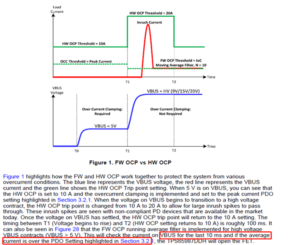
 there is a question from our compatibility test, from  TI's document (see the below picture) said ,the behavior control in10mS for the average current.if over the max setting value( max 20V/5A,peak current 150%

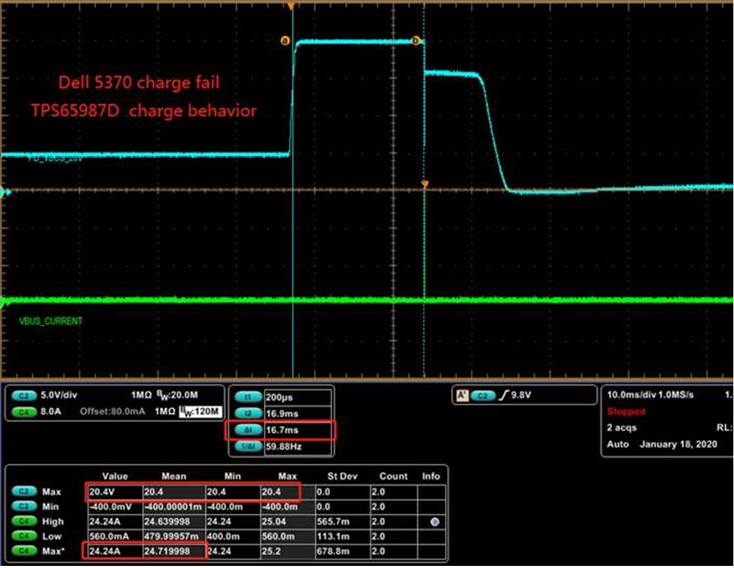
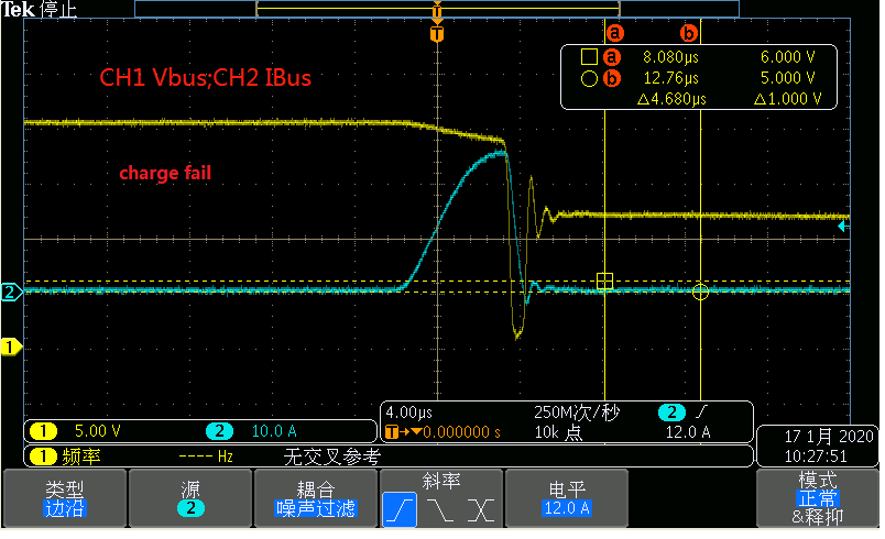
but  the NB of Dell_5370 out of the 10mS and peakcurrent(inrush) reach 25A max(see the caputre1).so,it's charge fail on it .

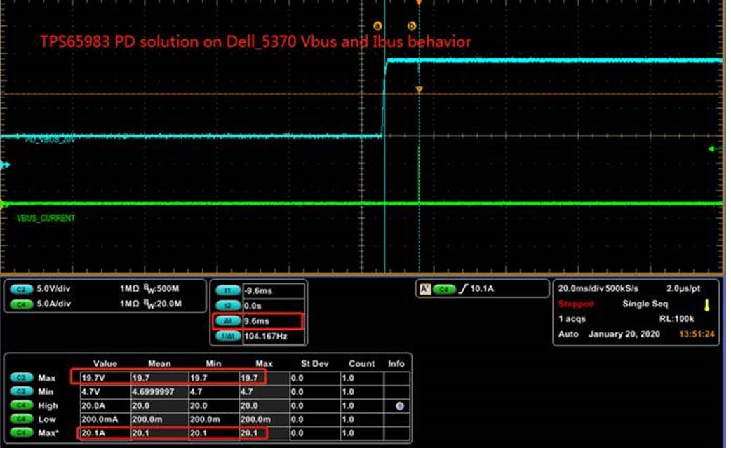
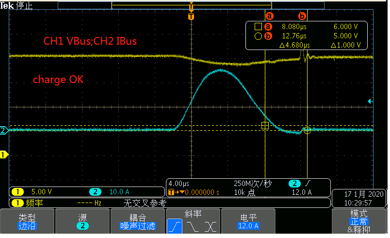
i  checked other's soulution(TPS65983), same as condiftion test, the behavior can meet TI's document(see the capture2).and charge OK.

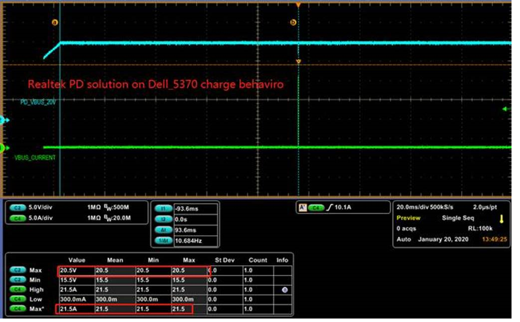
the same time, i checked other suppiler PD solution(Realtek), they Vbus ahead IBus more(reach 93mS),it's charge normal,

is the Realtek's PD solution didn't follow PD spec? or our TPS65987D didn't follow PD Spec?

if fix this issue, could you help me confirm and add some suggestion for this solution.

                      thanks!

  • Hello,

    The TPS65987D meets USB PD 3.0 Compliance.

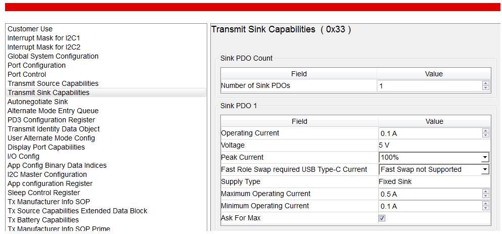
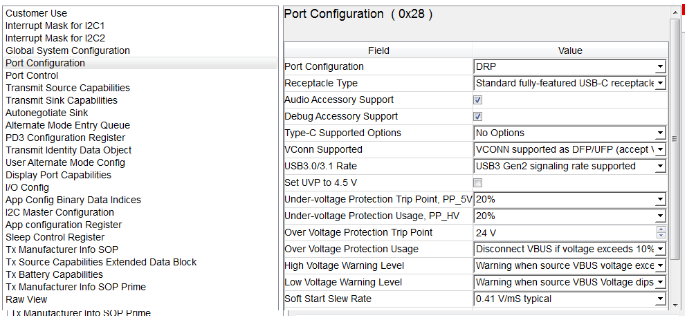
    To check, you are using the TPS65987D as a sink? If so, what settings do you have in your sink capabilities, register 0x33, and your port configuration, register 0x28?

    Thanks,

    Emma

  • Hi,Emma:

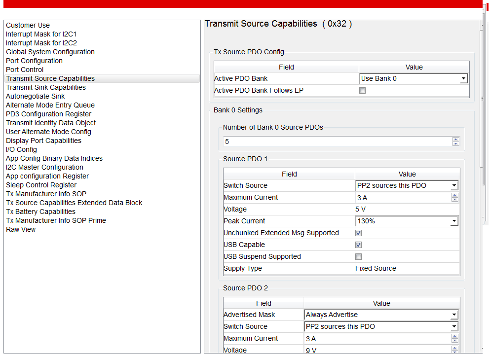
     No,we are using it on Docking station as a power source(the 0X33&0x32 setting as below),about the port configuration,

    how to setting can cover the NB of Dell_5370 PD charge ?

    could you help us confirm and instruct the setting on FW tool?

    thanks!

  • Hello,

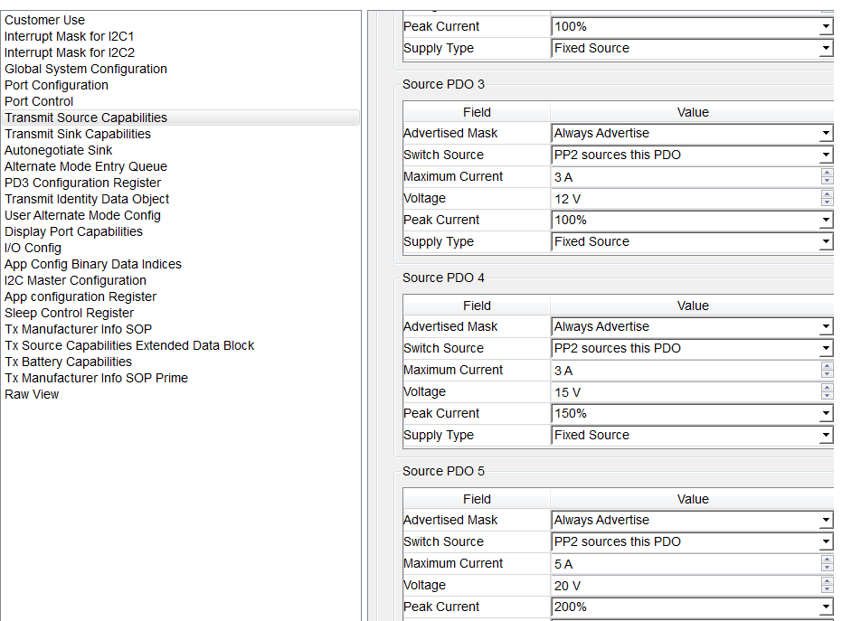
    Could you show me your full list of source caps? Also, could you provide scope shots that capture the overcurrent situation in higher resolution? Right now it is difficult to tell where your current is spiking and how high it's spiking. I also cannot see the current increase for the circuits that have working charging. It appears to be 0 A. 

    Thanks,

    Emma

  • Hi,Emma:

      supplement the source caps as below.and attached the zoom in the inrush current for NB of Dell_5370.(one for fail ,the other for OK(smoothly on other docking)).

    kindly hope you add your comment for the issue(charge fail).

    thanks!

  • Hello,

    You are hitting our overcurrent protection (OCP) with the sink you are connecting. The TPS65987D will increase its HW OCP trip point from 10 A to 20 A during the transition to a high voltage contract. Anything above 20 A, and the part will open the VBUS FET to protect the system. Your inrush current is spiking up to 24 A, so the device opening the FET to protect the system is expected behavior. 

    Thanks,

    Emma

  • Hi, Emma:

    Yes, i know this behaviro been reach to OCP on the system. your means said ,it been chareg  if the spike current decrease to 20A..and the system support to 20A be automatically by itself,is right?

    so the same as test condition, the TPS65982 and realtek been chareg normal for the inrush within 20A.

    could you provide some solution to us for the inrush decrease? or other good ideal cover this issue?

    thanks!

  • Hello,

    Yes, if the current spike is 20 A or less, the device's OCP point will not be triggered. 

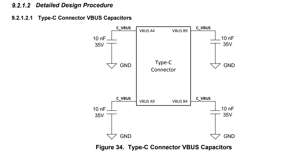
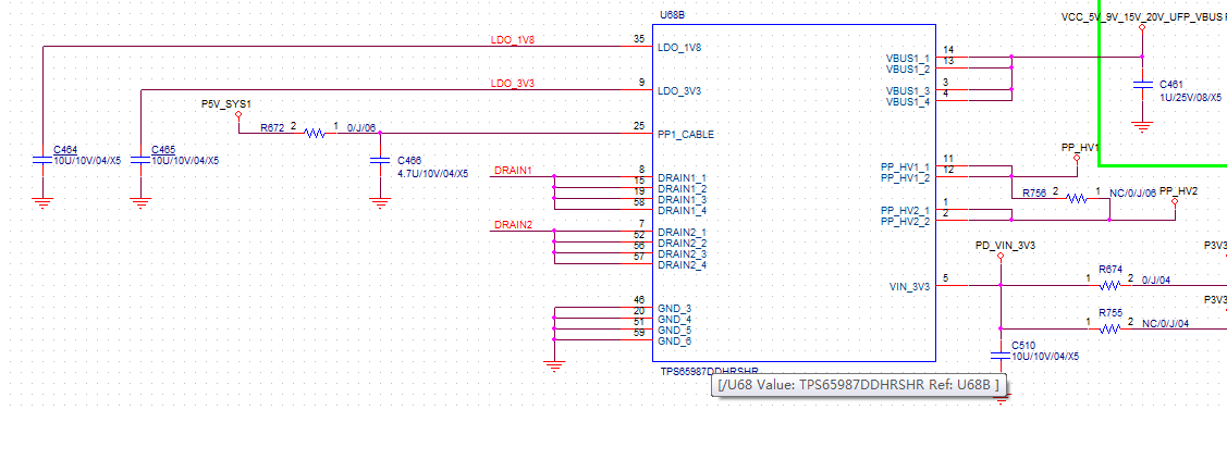
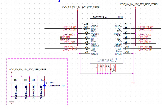
    Bypass capacitors are a good tool to use to decrease inrush current. Ensure that you have the recommended bypass capacitors on your inputs, shown below.

    Section 9.2.1.2 Detailed Design Procedure from the TPS65987D datasheet explains some of the capacitors you can have at your Type-C connector, shown below.


    Thanks,

    Emma

  • Hi,Emma:

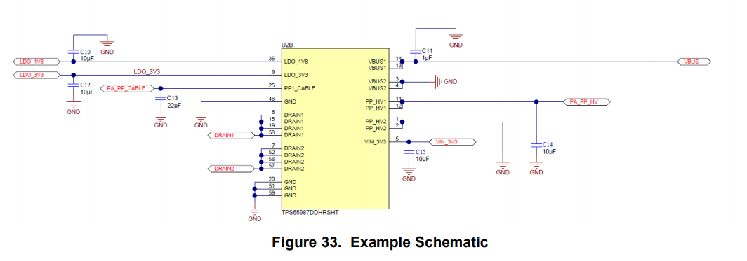
      i am follow the design from EVM on our the schematic(see as below),but the issue can't improve on this NB of Dell_5370.

    could you have antoher solution recommend ?and  Soft-Star setting on FW tool or HW portion for it ?

    kindly hope you give good feedback to me.

    thanks!

  • Hello,

    I am out of the office this week and will get back to you by the middle of next week after talking with team experts on how to resolve your OCP issues.

    Thanks,

    Emma

  • Hi,Emma:

        notice it!

    May you share it to your team resolve the issue during out of the office?

    becuause the issue pending more time on our schedule.

    so,we hope the issue debug on the forum asap ,then go on  next stage.

    thank you support!

  • Hi,Emma:

       do you go back your office?

    about my question,could you feedback it to us on this week?

    by the way:

       could you share the document for  Peakcurrent range of PD FW tool setting(130%,150%,200% to us ?

    we'll want to study it.

    thanks!

  • Hello,

    The peak current range comes from the PD spec, found here: https://www.usb.org/document-library/usb-pd-compliance-package. The reason the TPS565983 passes is because the inrush current peaks at 20A whereas the scope shot you attached for the TPS65987D peaks at 25A. If the TPS65987D had the same inrush of only 20A, then it would not turn off during the inrush current spike. The device is operating as expected in this scenario. 

    Thanks,

    Emma

  • HI, Emma:

     thanks!

     your meaning is said, the behavior fail from the peakcurrent higher(reach to 24A) only , doesn't as the document said"VBUS for the last 10 ms and if the average current is over the PDO Setting" for the fail,is right?

    if like this, could you have a good solution for the soft-star or reduce the inrush ?

    kindly advise you and your team give some comment for it.

    thanks!

  • Hello,

    Yes the device will shut off in this case. 

    You can use the TPS65987D to soft start if it is being used as a sink, but not a source. So this will not work in your case. You could try soft starting your sink device so that it will not spike the inrush current.  

    Thanks,

    Emma

  • Hi,Emma:

    i see the soft-star for sink on the TPS65987D.

    regarding your said the" try soft star on sink device",

    what are you have any sucessful tips for it?

    could you share it to me for try the sot star?

    BTW:

      about the peakcurrent spec follow the  PD standard ,i check it after, it's described a few item(as below)

    and read the document"Power Path Performance and Protection" after, there is described Iocc for 5V only(see the P10's table 1).

    regarding the higher voltage Iocc can't find any described on it.

    do you have another document for the peakcurrent introduce?

    i want to know the range of peakcurrent, how much is corresponed current  when i setting 130% or 150% on higher voltage.

    thanks!

  • Hello,

    I am not sure what type of sink device you are using so I am not able to recommend a solution for soft starting the device unless the sink is also using the TPS65987D. 

    What document did you screenshot above? 

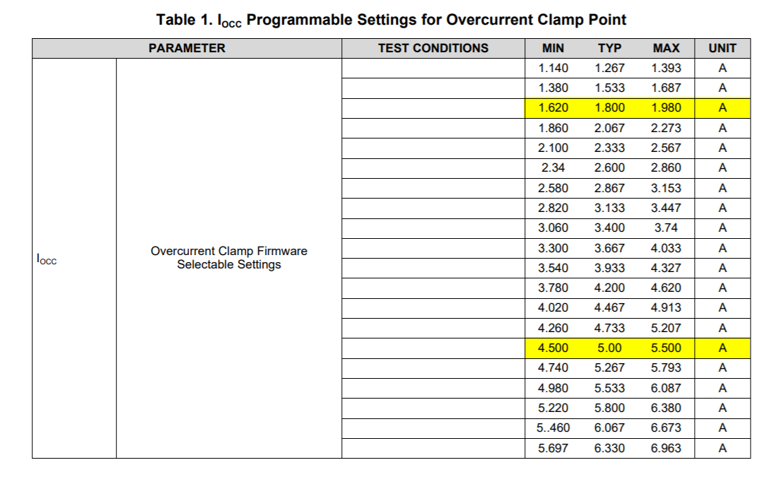
    Iocc is dependent on what you set the Max Current to be in your PDOs. The Overcurrent Clamp Point's min must be greater than, or equal to, the max current you set in the GUI. It is described in detail in the TPS65987DDH Power Path Performance and Protection app note. 

    Here are a few examples:

    You set the GUI to have a PDO with max current of 3A at 150% peak current which would equate to 4.5A. The internal firmware would set the Iocc programmable setting to be one greater than or equal to 4.5 A. Looking at the table below, this means that the over current clap point would be between 4.500A and 5.500A.

    Now lets say you set the GUI to have a PDO with max current of 3A at 50% peak current which would equate to 1.5A. The internal firmware would set the Iocc programmable setting to be one greater than or equal to 1.5 A. Looking at the table below, this means that the over current clap point would be between 1.620A and 1.980A.

    Thanks,

    Emma


  • Hi,Emma:

    understand!

    the capture from the PD standard,pls refer the link:  usb.org/.../usb-power-delivery.

    you said the document" TPS65987DDH Power Path Performance and Protection" , i am read it already.

    whereas this table for Iocc only,the range doesn't for peakcurrent of higher voltage.

    you can refer the link for described

    https://e2e.ti.com/support/interface/f/138/t/775148?keyMatch=TPS65987D%20OCP&tisearch=Search-EN-everything..


    as you said the table, how much is  corresponde the curre nt when i setting the 20V/5A with 150% on application configuration tool.

    it can't find the corresponde value of current. in theory the value of current is 5A*1.5=7.5A when setting the 5A with 150%.

    could you help me clarify it for the peakcurrent? 

    may you share the table to me reference if you have more document for the peakcurrent setting.

    thanks!


  • Hello,

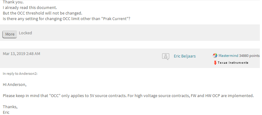
    The table and over current clamping, OCC, only apply when sourcing 5V, as described above. That is why the table does not extend past the values shown. 

    When negotiating a high voltage contract on VBUS (VBUS > 5 V), the TPS65987DDH will dynamically adjust the hardware OCP trip point from 10 A to 20 A while the VBUS voltage is transitioning from 5 V to the negotiated high voltage level.

    Thanks,

    Emma

  • HI, Emma:

    thank you reply.

    yes, according you said , i am read the document already. and don't find any the peakcurrent describ,so need more support on the forum.

    meamwhile, i tested the value of OCP when i setting 130% and 150% respectively by Power-Z with E-load.

    their value same as ,both reach above 8A around from V5.13 application configuration tool.

    what're they different between 130% and 150%?

    how to choose among the 130% and 150% for our docking?

    i am very confuse.

    kindly adivse you provide more clarify it .

    thanks!

  • Hello,

    The hardware OCP point being moved from 10 A to 20 A is described in 3.1 FW OCP vs HW OCP and also 3.3 Hardware Overcurrent Protection (HW OCP)

    Can you please clarify your test? What PDO settings are you using?

    Thanks,

    Emma

  • Hi,Emma:

       yes, the document is said the 10A to 20A for HW OCP max when the PDO voltage change to higher from 5V,if settled will return to 10A.

                and the HW OCP is dynamically changing the OCP piont during the voltage transition,it seem for inrush relationship.

       but the FW OCP point doesn't describe any higher voltage,only explain the 5V item.

     now, my question  is what be  different  between peakcurrent 130% and 150% when i setting 20V@5A PDO on Application configruation tool(v5.13)?

    i tested the value of OCP(setting peakcurrent 130%,5A@20V) above 8A around by power-Z+E-load .

    if setting it for 150%,the result same as.

    how to get the different for peakcurrent on the higher voltage(if setting 20V@5A)?

    this is my confuse,hope get you more support it.

    thanks!

  • Hello,

    So the Over Current Clamp (OCC), refers to the current limiting that we do on the 5V source contracts only. 

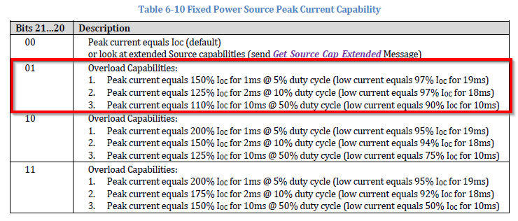
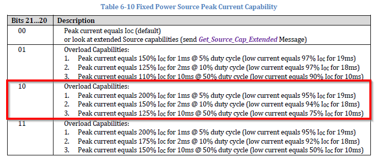
    The OCP follows the guidelines talked about in Table 6-10 Fixed Power Source Peak Current Capability from the PD spec, posted earlier.

    The GUI peak current settings directly reflects these bit options described in the PD spec table. 

    Setting a peak current of 130% means the device will have the following overload capabilities:

    Setting a peak current of 150% means the device will have the following overload capabilities:

    Thanks,

    Emma

  • Hi,Emma:

      understand it!

    but i can't find any  the value of peakcurrent on PD spec for the 130% correspond bit 01,and 150% correspond   bit 10.

    and they're 3 types(ie:1,2,3) value respectively on every bit,

    how to correspone  among the 3 types when i setting 150%(PD spec is bit 10) on TI's Tools?

    and i setting different peakcurrent(130%,150%)on TI's Tool(application configuration tool),

    their OCP value same as touch above 8A when i tested the OCP point by Power-Z+E-load.

    if follow PD spec for the peakcurrent, like that,they should be different OCP point.

    but the result don't it.

    could you help me clarify it again?

    thanks!

  • Hello,

    The value of the peak current is the percent of the Ioc.

    To read more about the peak current testing, check out the PD spec. There are multiple sections that you can read to learn more about the peak current. Section 6.5.1.10 Peak Current Field discusses that the 3 (1, 2, 3) types are different combinations of % overload. So numbers 1-3 can apply to your test. If 150% (10) is selected, then the overload condition can maintain:

    Peak current equals 200% IOC for 1ms @ 5% duty cycle (low current equals 95% IOC for 19ms)        or
    Peak current equals 150% IOC for 2ms @ 10% duty cycle (low current equals 94% IOC for 18ms)      or
    Peak current equals 125% IOC for 10ms @ 50% duty cycle (low current equals 75% IOC for 10ms)    or

    Thanks,

    Emma

  • Hi,Emma:

    thank you for me explain the number1-3 of peakcurent .

    but i am another question,could you help to check it for me.

     i setting different peakcurrent(130%,150%)on TI's Tool(application configuration tool Ver5.13)after,then build in the bin file,

    loading it to our docking after, test their OCP value,they are both touch above 8A when i tested the OCP point by Power-Z+E-load.

    if  the peakcurrent follow PD spec should be different OCP point.but the result doesn't as our expectation.

    what is the TPS65987D different with PD spec for the OCP point?

  • Hello,

    Actually 01 and 10 share the overload condition at 150%. However, 01 can only withstand 150% Ioc for 1ms where 10 can withstand 150% Ioc for 2ms. So their overvoltage point may be the same with different timing cutoffs. 

    Thanks,

    Emma

  • HI,Emma:

        understood!

    thank you answer always.

    regarding the peakcurrent and OCP, are they same as content or meaning on the PD tools(application configuration tools)?

    i think the OCP is overcurrent point for the  continues overload,

     peakcurrent is spike current for the transient overload,doesn't continues. 

    is it right or not? could you give me some comment?

    if the peakcurrent for continues overload, the V5.13 tool(application configuration tools) be suitable.

    if the peakcurrent for spike current, the V6.1.1 tool (application configuration tools)be corresponde.

    because i tested the OCP point on 5.6A by power-Z+E-load when i setting 130% and 150% on V6.1.1.

       they are same as shutdown Vbus if load 5.6A .whatever the peakcurrent  is130% or 150% setting.

    so ,i am understand it for spike current.

    which one version is right between the V5.13 and V6.1.1?

    may you give me some suggestion for it?

    thanks!

  • Hello,

    OCP is how the device meets the peak current parameters from the PD spec. 

    You should use version 6.1.1 of the GUI tool, as it is the most recent release. 

    Thanks,

    Emma

  • HI,Emma:

    thanks!

    how to meets them(OCP and peakcurrent) in the PD spec?

    which is paragraph corresponed them?

    may you show it to me study?

    regarding the GUI tool,like your meaning,the peakcurrent should be meet the spike current,is right?

    doesn't suitable the continues current.

    one more thing:

    upon the original the charge issue(Dell_5370), it's inrush over the IC spec(max support to 20A,actually current is 24.2A).

    according the inrush formual(I=Cload*(DVout/Dt)),i change the PD voltage (from 20.3 to 19.68V)after,it charge normal for the NB in Ambient 25dgree.

    but charge 1hour after, maybe the temperature rise on the board,appoximately 40-50dgree .

    then pull out the cable from the docking. next re-plug in it to the docking for re-charge.it's fail.

    i am check the PPHV's Rds of tps65987D. in the datasheet show 25-33mR at Tj=25 dgree.

    doesn't show the resistance of higher Tj of tps65987d.

    how many is it on higher temperature?

    like this, could you help to me explain the reason?(Ta=25dgree be OK, rise to 50dgree can't charge)

    if support the NB, may you with your team add some comment or better solution for it?

    thanks!

  • Hello,

    Section 6.5.1.10 Peak Current Field discusses that the 3 (1, 2, 3) types are different combinations of % overload. The Power Path Performance and Protection app note explains how the TPS65987D meets the PD spec requirements. 

    The GUI tool options apply to the PD spec table 6-10, so the GUI options do not only look at peak current. 

    Please submit a new E2E for separate issues. 

    Thanks,

    Emma

  • Hi,Emma:

      as well, appreciate and thank your all support !

    i'll sumbit the new item for the Dell_5370 PD charge issue.

    thanks!