This thread has been locked.

If you have a related question, please click the "Ask a related question" button in the top right corner. The newly created question will be automatically linked to this question.

SN65HVD3080E: RS485 application note for protection

Part Number: SN65HVD3080E
Other Parts Discussed in Thread: SN75ALS176B

Hi

My customer have some question about the following application note.

Could you please support it?

What is the u.l.?  (UL? UI?)

What is the A. dB?

Could you please let me know the calculation method for each parameters?

Also, customer plan to use SN65HVD3080E.

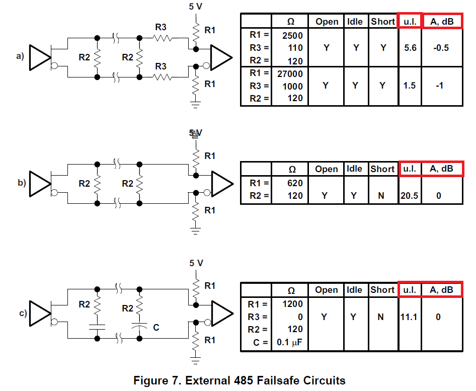
Should they consider fail safe circuit with a)?  

Could you please explain about section 2.2 by concretely?

How should the customer consider about -6dB?

Thanks

Muk

  • Hi Muk,

    1. UL describes the equivalent Unit Load of the shown network. See section 2.1 on this concept.

    2. A, dB describes the signal attenuation in dB added by the shown network. See section 2.2 on this concept.

    3. SN65HVD3080E features internal fail-safe biasing. This keeps the receiver in a known state and gives slight noise immunity while not significantly effecting the bus voltages. Depending on the needs of your system, it is recommended to include an external fail-safe biasing network to increase receiver noise immunity and to bias other nodes that may not have an integrated fail-safe feature. Which method you choose to implement will depend on system requirements and limitations. The referenced article can be used as a guide in this process.

    4. Section 2.2 refers to Signal Attenuation and Distortion. The two main factors the article describes that impact this consideration are cable characteristics and added attenuation from a fail-safe network. Cable manufacturers often include these properties over a range of signal frequencies and the added attenuation from fail-safe method a) are listed in Figure 7. It is a good rule-of-thumb (good practice) to keep the total signal attenuation below -6dB. If the system approaches or exceeds this value in design, you may consider using fail-safe methods without series resistances (b and c) to avoid increasing attenuation further. 

    Let me know if you have any more questions. 

    Regards,

    Eric

  • Hi Eric-san,

    Regarding #1 and #2 (UL and A. dB)

    Could you please let me know the calculation method by concrete example?

    Thanks

    Muk 

  • Hi Muk,

    1. An example of UL calculation is found in section 2.1. Here we calculate the UL of SN75ALS176B. One UL is defined as a stead-state load which allows 1mA of current under the maximum common-mode voltage of 12V (or 0.8mA under -7V). SN75ALS176B specifies a receiver input resistance of 12k-ohms. Under 12V bus stress, this would allow 1mA of current through the device (Vstress / Rinput = I). Because of this, we can define SN75ALS176B to have an equivalent resistance to 1 UL. 

    To calculate the UL of a termination scheme, the same methodology can be applied. For circuit 'a' above, if we apply a 12V stress at the driver, we will find a current through the fail safe resistors equal to the voltage divided by the resistor values (Vstress / Rfs = I). This gives us Vstress / Rfs = 12V / (2500 + 110) = 4.60mA. This equates to a UL of 4.6. The chart above assumes the receiver has a UL of 1, giving us a total UL of 5.6 for this circuit.

    2. Signal attenuation due to the added failsafe circuit can be estimated using the steady-state condition. This only appears in circuit 'a' because of the added series resistances. The resulting voltage divider between the driver and the network is where we can calculate our losses from. 

    The attenuation from this series resistance can be calculated through the resistors divider formed by R3, R1, and the receiver resistance Rrec; A = 20 * log{ (R1 || Rrec) / Rtot } where Rrec is the receiver resistance and Rtot is the total resistance R3 + (R1 || Rrec). Since the receiver is assumed to have a UL of 1, the resistance is assumed to be 12k-ohm. Plugging in values, we'll receiver (R1 || Rrec) = (2500-ohm || 12000-ohm) = 2069-ohm; Rtot = 110-ohm + 2069-ohm = 2179-ohm. Lastly, A = 20 * log( 2069 / 2179 ) = -0.45dB. The chart rounds this to -0.5dB. 

    The same process can be applied to the second row to find A = -0.98dB.

    Let me know if this makes sense or if you have any other questions.

    Regards,
    Eric