This thread has been locked.

If you have a related question, please click the "Ask a related question" button in the top right corner. The newly created question will be automatically linked to this question.

TPS65987D: Slave Address ID is always 0x00

Part Number: TPS65987D
Other Parts Discussed in Thread: BQ4050, TPS65987, BQ25703, BQ25703A, , TPS65981

I have a customer using the TPS65987, BQ25703, and BQ4050 similar to the TIDA-01515 but with only 1 USB C port. They are having issues with I2C on the TPS65987. They can communicate to the BQ4050 with no issues but are having difficulties on the BQ25703.

From the customer:

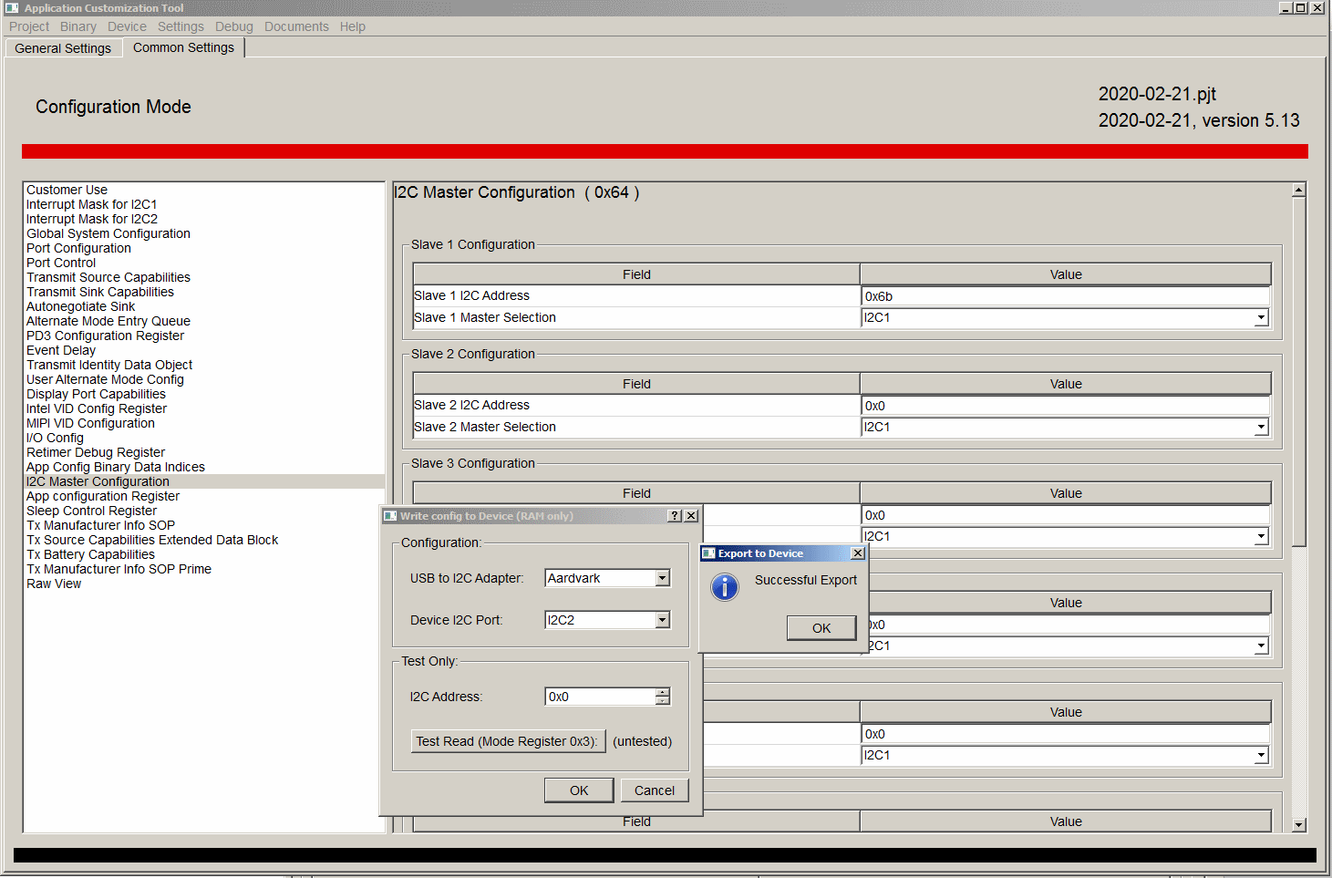
I2C seems to be able to read and write to the TPS65987 correctly. I  can change parameters, write them and then read the changes back in debug mode. The one parameter I don't read back correct is the slave ID, always comes back as 0x00.

When I do the I2C address scan I see devices at both 0x22 (the TPS65978) and 0x6B (the BQ25703A). So the BQ25703A is responding

Thanks,
Nick

  • Some additional detail: 

    I was originally trying to use I2C1 to control the BQ25703 (on address 0x6B). I have also tried I2C3 just to be sure. Both resulted in me reading the value (which was sett to 0x6B) as 0x00 when I went into DEBUG mode.

    I only have I2C1 from the TPS65987D connected on my board. I am trying to use this for both controlling the BQ25703 and talking to the TPS65987D (in DEBUG mode) (and since SPI is not working, programming the TPS65987D, for now). It is also the same I2C bus being used to control the BQ4050, though I program that separately and am not expecting the TPS65987D to control that.

    Do you think reading the TPS65987D in DEBUG mode over the same I2C bus is creating a problem?

    Thanks,
    Nick

  • Hi Nicholas,

    To make sure I understand, you are wanting to have the TPS65987D act as both the master and slave on I2C1? This will not work as you cannot have a device act as both a master and a slave. The master is responsible for driving the I2C clock and initiating the conversation so a slave cannot also serve in this role.

    If you want to control the TPS65987D, you will need to connect to I2C2. This should allow you to read the proper slave address for the device

  • Hi Adam, 

    I connected to the I2C2 port on the TPS65987D and was able to flash the RAM and enter DEBUG mode through the I2C2 port (leaving the I2C1 port free to be the master for the BQ25703A). This results in the same behavior as before though, I can flash the firmware and then read changes I make in DEBUG mode, but I always read 0x00 for the I2C master address.

    Best,
    Nick

  • Hi Nick,

    Want to make sure I am understanding this correctly. You are wanting to read the address of the TPS65987D on I2C1 where it is acting as the master? You will not read anything back from the TPS65987D as it is the master and does not need an address following the I2C specification.

  • Hi Adam,

    The goal here is to read the slave addresses of the downstream devices connected to the TPS65987D. Below is the setup:

    1. External Aardvark/GUI communicating to the TPS65987D though I2C2 = TPS65987D acting as a slave
    2. TPS65987D communicating to BQ25703A and BQ4050 though I2C1 = TPS65987 acting as a Master to BQ25703A and BQ4050
    3. When we try to read the slave address of the BQ25703A or BQ4050 to an external PC or the GUI we get 0x00 rather than their actual I2C address.

    Nick

  • Then this falls on both of those devices not advertising the proper I2C address. Make sure that they are powered and that the SCL and SDA lines are going to the proper pins for each respective part. You can also try disconnecting the TPS65987D so that the Aardvark you have connected to the I2C lines is the only master.

    Also make sure that the I2C channels are pulled up to 3.3V.

    This failure would not be due to the PD controller though but instead the BQ25703A and BQ4050

  • Hi Adam,

    We stepped back and tried communicating with the BQ25703A and the BQ4050 directly and everything is working correctly. This is leading us to believe the TPS65987D is the cause of the issue. 

    • I've attached a screen grab showing where I try to set the address and then where I'm trying to read it back in the DEBUG mode of the TPS65981_2_6_7_8 Application Customization 5.13 tool.
    • The fact I can't read and address here and that the BQ25703A doesn't seem to be sinking or sourcing power makes me think the TPS65987D is not correctly communicating the the BQ25703A, also there is no traffic (or SCL) on the I2C1 bus.
    • Is there a setting somewhere that enables the I2C communication from the TPS65987D? The only one I've seen in under 'Global System Configuration -> I2C1 Enable as Master' which I've enabled.

    I've used Adv-TIDA-01627.pjt as a starting point. Is there a different configuration file you would recommend? I do notice that the values under 'App configuration Register' all seem to be set to default.

    Thanks,
    Nick

    Writing

    Reading

  • Hi Nick,

    Now I understand what you mean when you say you read the slave address of the TPS65987D, thank you for the clarification.

    First, I would recommend that you download the latest configuration from the link below. Once you download the tool, you can import the settings used from your existing project. This is done by making a new project for the TPS65987D, and then clicking on Project -> Import Settings from project.

    http://www.ti.com/tool/TPS6598X-CONFIG

    Next, what do you have programmed as a 'trigger event' for the I2C Master Events? Power On Reset should issue the corresponding data whenever the PD controller turns on.

  • 1. Thanks, I was using an older version and have now updated. The results seem the same as before though.
    2. I have tried to follow 'slvae18.pdf' for the I2C Master events. The details should be in the .pjt file I sent (email)

    This has lead me to a question though...I'm programming the TPS65987D through I2C, meaning I can't power cycle the device without losing the program. Does the fact that some of the setup of the BQ25703A only happen at a Power on Reset event mean it isn't happening? Does the TPS65987D automatically preform a Power on Reset after it gets programmed over I2C?

  • Hi Adam,

    Any updates on this?

    Thanks,
    Nick

  • Hi Nick,

    I have a few recommendations for you. 

    First, how are you loading the configuration onto the PD controller? Are you using an external I2C flash or an external EC through the use of the PTCx commands?

    If you are using the external EC, I recommend that you boot from the Safe Configuration if you are intending to load the patch bundle through the PTCx commands. You will not load a default configuration that would require you to reset our device after loading the patch bundle. If the device boots in a dead battery configuration (through VBUS) it will operate as a legacy sink, requesting 5V through a Rd resistor. 

    Second, in your base configuration that you are loading either through an external flash or EC, recommend that you add numbers to the customer use filed (register 0x6) to signify whether your configuration is being loaded properly to the PD controller or not. 

    Third, for the sake of initial testing, recommend that you do not put the PD controller in a dead battery scenario (powered from VBUS) but to instead supply power to VIN3V3