Other Parts Discussed in Thread: DP83822H
Hello,
Processor: F28M36P63C2ZWTS
PHY: DP83822H
Software Pin Configuration
MDIO on PM0 has been set up as GPIO_PIN_TYPE_OD
//*****************************************************************************
//
// Set the GPIO port control registers appropriately for the hardware.
//
// This function determines the correct port control settings to enable the
// basic peripheral signals for the development board on their respective pins
// and also ensures that all required EPI signals are correctly routed.  The
// EPI signal configuration is determined from the daughter board information
// structure passed via the \e psInfo parameter.
//
//*****************************************************************************
static void
PortControlSet(void)
{

    //
    // To begin with, we set the port control values for all the non-EPI
    // peripherals.
    //


    //UART Setup
    GPIOPinTypeUART(GPIO_PORTE_BASE, GPIO_PIN_4 | GPIO_PIN_5);
    GPIOPinConfigure(GPIO_PE4_U0RX);
    GPIOPinConfigure(GPIO_PE5_U0TX);

    //SSI SD Card Setup
    GPIOPinTypeSSI(SDC_GPIO_PORT_BASE, SDC_SSI_TX | SDC_SSI_RX | SDC_SSI_CLK);
    GPIOPinTypeGPIOOutput(SDCARD_CS_BASE, SDCARD_CS_PIN);
    GPIOPadConfigSet(SDC_GPIO_PORT_BASE, SDC_SSI_PINS,
                     GPIO_PIN_TYPE_STD_WPU);
    GPIOPadConfigSet(SDCARD_CS_BASE, SDCARD_CS_PIN,
                     GPIO_PIN_TYPE_STD_WPU);
    GPIOPinConfigure(GPIO_PR0_SSI3TX);
    GPIOPinConfigure(GPIO_PR1_SSI3RX);
    GPIOPinConfigure(GPIO_PR2_SSI3CLK);
    GPIOPinWrite(SDCARD_CS_BASE, SDCARD_CS_PIN, SDCARD_CS_PIN);


    // USB Pins
    GPIOPinConfigure(GPIO_PN6_USB0EPEN);
    GPIOPinConfigure(GPIO_PN7_USB0PFLT);
    GPIOPinTypeUSBDigital(GPIO_PORTN_BASE, GPIO_PIN_6 | GPIO_PIN_7);
    GPIOPinTypeUSBAnalog(GPIO_PORTF_BASE, GPIO_PIN_6);
    GPIOPinTypeUSBAnalog(GPIO_PORTG_BASE, GPIO_PIN_2 | GPIO_PIN_5 | GPIO_PIN_6);


    //Ethernet pin setup
    GPIODirModeSet(GPIO_PORTK_BASE,
                   GPIO_PIN_4 | GPIO_PIN_5 | GPIO_PIN_7,
                   GPIO_DIR_MODE_HW);
	GPIOPadConfigSet(GPIO_PORTK_BASE,
                     GPIO_PIN_4 | GPIO_PIN_5 | GPIO_PIN_7,
                     GPIO_PIN_TYPE_STD);
	GPIOPinConfigure(GPIO_PK4_MIITXEN);
	GPIOPinConfigure(GPIO_PK5_MIITXCK);
	GPIOPinConfigure(GPIO_PK7_MIICRS);


	GPIODirModeSet(GPIO_PORTL_BASE,
                   GPIO_PIN_0 | GPIO_PIN_1 | GPIO_PIN_2 | GPIO_PIN_3 |
                   GPIO_PIN_4 | GPIO_PIN_5 | GPIO_PIN_6 | GPIO_PIN_7,
                   GPIO_DIR_MODE_HW);
	GPIOPadConfigSet(GPIO_PORTL_BASE,
                     GPIO_PIN_0 | GPIO_PIN_1 | GPIO_PIN_2 | GPIO_PIN_3 |
                     GPIO_PIN_4 | GPIO_PIN_5 | GPIO_PIN_6 | GPIO_PIN_7,
                     GPIO_PIN_TYPE_STD);
	GPIOPinConfigure(GPIO_PL0_MIIRXD3);
	GPIOPinConfigure(GPIO_PL1_MIIRXD2);
	GPIOPinConfigure(GPIO_PL2_MIIRXD1);
	GPIOPinConfigure(GPIO_PL3_MIIRXD0);
	GPIOPinConfigure(GPIO_PL4_MIICOL);
	GPIOPinConfigure(GPIO_PL5_MIIPHYRSTN);
	GPIOPinConfigure(GPIO_PL6_MIIPHYINTRN);
	GPIOPinConfigure(GPIO_PL7_MIIMDC);

	GPIODirModeSet(GPIO_PORTM_BASE,
                   GPIO_PIN_0 | GPIO_PIN_1 | GPIO_PIN_2 | GPIO_PIN_3 |
                   GPIO_PIN_4 | GPIO_PIN_5 | GPIO_PIN_6 | GPIO_PIN_7,
                   GPIO_DIR_MODE_HW);
	GPIOPadConfigSet(GPIO_PORTM_BASE,
                     GPIO_PIN_1 | GPIO_PIN_2 | GPIO_PIN_3 |
                     GPIO_PIN_4 | GPIO_PIN_5 | GPIO_PIN_6 | GPIO_PIN_7,
                     GPIO_PIN_TYPE_STD);
    GPIOPadConfigSet(GPIO_PORTM_BASE,
                     GPIO_PIN_0,
                     GPIO_PIN_TYPE_OD);
	GPIOPinConfigure(GPIO_PM0_MIIMDIO);
	GPIOPinConfigure(GPIO_PM1_MIITXD3);
	GPIOPinConfigure(GPIO_PM2_MIITXD2);
	GPIOPinConfigure(GPIO_PM3_MIITXD1);
	GPIOPinConfigure(GPIO_PM4_MIITXD0);
	GPIOPinConfigure(GPIO_PM5_MIIRXDV);
	GPIOPinConfigure(GPIO_PM6_MIIRXER);
	GPIOPinConfigure(GPIO_PM7_MIIRXCK);


}

//*****************************************************************************
//
//! Configures the device pinout for the development board.
//!
//! This function configures each pin of the device to route the! appropriate
//! peripheral signal as required by the design of the development board.
//!
//! \note This module can be built in two ways.  If the label SIMPLE_PINOUT_SET
//! is not defined, the PinoutSet() function will attempt to read an I2C EEPROM
//! to determine which daughter board is attached to the development kit board
//! and use information from that EEPROM to dynamically configure the EPI
//! appropriately.  In this case, if no EEPROM is found, the EPI configuration
//! will default to that required to use the SDRAM daughter board which is
//! included with the base development kit.
//!
//! If SIMPLE_PINOUT_SET is defined, however, all the dynamic configuration
//! code is replaced with a very simple function which merely sets the pinout
//! and EPI configuration statically.  This is a better representation of how a
//! real-world application would likely initialize the pinout and EPI timing
//! and takes significantly less code space than the dynamic, daughter-board
//! detecting version.  The example offered here sets the pinout and EPI
//! configuration appropriately for the Flash/SRAM/LCD daughter board.
//!
//! \return None.
//
//*****************************************************************************
void
PinoutSet(void)
{

    //
    // Enable all GPIO banks.
    //
    SysCtlPeripheralEnable(SYSCTL_PERIPH_GPIOA);
    SysCtlPeripheralEnable(SYSCTL_PERIPH_GPIOB);
    SysCtlPeripheralEnable(SYSCTL_PERIPH_GPIOC);
    SysCtlPeripheralEnable(SYSCTL_PERIPH_GPIOD);
    SysCtlPeripheralEnable(SYSCTL_PERIPH_GPIOE);
    SysCtlPeripheralEnable(SYSCTL_PERIPH_GPIOF);
    SysCtlPeripheralEnable(SYSCTL_PERIPH_GPIOG);
    SysCtlPeripheralEnable(SYSCTL_PERIPH_GPIOH);
    SysCtlPeripheralEnable(SYSCTL_PERIPH_GPIOJ);
    SysCtlPeripheralEnable(SYSCTL_PERIPH_GPIOK);
    SysCtlPeripheralEnable(SYSCTL_PERIPH_GPIOL);
    SysCtlPeripheralEnable(SYSCTL_PERIPH_GPIOM);
    SysCtlPeripheralEnable(SYSCTL_PERIPH_GPION);
    SysCtlPeripheralEnable(SYSCTL_PERIPH_GPIOP);
    SysCtlPeripheralEnable(SYSCTL_PERIPH_GPIOQ);
    SysCtlPeripheralEnable(SYSCTL_PERIPH_GPIOR);
    SysCtlPeripheralEnable(SYSCTL_PERIPH_GPIOS);


    //
    // Determine the port control settings required to enable the EPI pins
    // and other peripheral signals for this daughter board and set all the
    // GPIO port control registers.
    //
    PortControlSet();

}
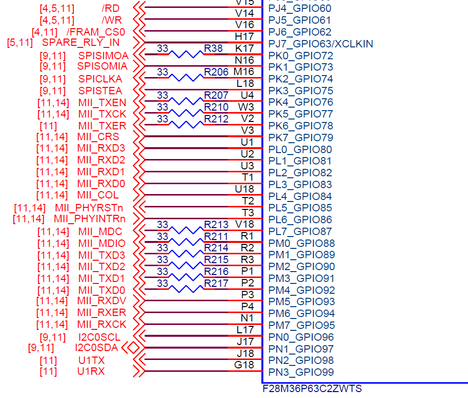
Schematic is setup as follows:
The goal is to use lwip. Using Saleae Logic Analyzer I am seeing contention on the MDIO analog reading where the signal in the data portion of the message is not able to drive high. We believe it is a configuration issue, but are unsure if it is a configuration issue of the processor, or the PHY. R275 is populated on the MDIO line with a 2.2k resistor.
For further insight the lwip example has been used as a base, and The pin configuration described above, and UART setup has been the only modifications to software.
C:\ti\controlSUITE\device_support\f28m36x\v220\F28M36x_examples_Master\enet_lwip\m3\ccs
Testing with a router: Router Wired port <---Ethernet Cable---> Board
Expectation is the Board Eth port LEDs would respond, and the Router LED would respond. As an additional check the Ethernet cable was connected to the laptop instead of the board and the LEDs on both router and laptop were on.
We believe the contention seen to be the issue and are unsure if it is on the processor, or PHY side setup issue? Let me know if any additional information would be helpful to confirm setup.


