This thread has been locked.

If you have a related question, please click the "Ask a related question" button in the top right corner. The newly created question will be automatically linked to this question.

AM26C32: Heating

Part Number: AM26C32
Other Parts Discussed in Thread: AM26LS31, AM26LS32AC, AM26C31

Hello, 

Our customer is using AM26C32IPWG4 and AM26C31IPW. He says that both devices' temperatures rise up to 50 degrees each. Can we please ask for your advice on what we can look into that may have caused the heating?

Thank you

  • Hi Elisha,

    When a device consumes power in a system, it will need dissipate this energy as heat. The overall temperature that a device reaches will depend on the amount of power being used and the ambient temperature of the environment (as well as a variety of other factors). In a hypothetical scenario where AM26C32 is using its maximum specified power (supply and input currents at or near Max values) it will consume around 100mW. With a thermal resistance of around 100C/W for the TSSOP package, this equates to a 10C difference between device and ambient temperature. Note that this calculation includes rough estimates and ignores thermal relief from other major factors such as the PCB design and airflow. 

    Based on the above explanation, is it possible that the device is heavy enough load to be consuming near its maximum rated power? Are all functions of the device working properly? Is it possible to measure the current draw of the device or system?

    Other things to check may be the device connections to the PCB pads (no excess electrical or thermal resistance, especially in supply and ground pins) or if the device near another device that is also at a similar or higher temperature.

    Regards,
    Eric

  • Hello? Eric.
    What should I do with the input and output pins of the unused channels of the AM26LS32?
    Can I just open the unused pins? Or should I connect to VCC or GND?
    I use three of the four channels of the AM26LS32 and one channel is not used, but nothing is connected to the input / output pins of the unused channel. Could this be a problem with the AM26LS32 heating up? In the AM26LS32 Datasheet, no way to handle unused pins was described.
    And I am using several AM26LS32 and AM26LS31 on one board, but all AM26LS32 and AM26LS31 have abnormal fever. There is no particular heat around these devices.
    In addition, there is no particular problem with the DC5V supply line and GND pattern.
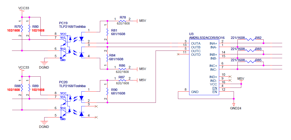
    The load device connected to the output of the AM26LS32 is Toshiba's TLP2168 Photocouper, which has a drive current of 7mA. Is there any problem with the way to drive Photocopuler with AM26LS32 output?
  • The schematic above is the AM26LS32 connection diagram of my board.

  • Hi Goowoon,

    Thank you for sharing the schematic. It looks like the current requirements for TLP2168's LED are greater than the recommended output current for AM26C32. This current draw may be the cause of the temperature increase you are seeing. The schematic shows that this design includes AM26LS32AC which has a slightly higher output current, but is still below the 14mA Max rating specified by TLP2168. This specific device also has a slightly lower operating temperature range - an equivalent rating in the same family would be AM26LS32AI. 

    You mentioned you are also seeing elevated temperatures in the AM26C31 line drivers as well. Would you be able to share a schematic of one of these circuits? I don't believe the current draw described above would not apply to the drivers. 

    It is OK to leave unused RS-422 inputs/outputs and digital outputs floating. Digital inputs such as Enables and AM26C31's A pins should be tied to Vcc or ground. This appears fine in your schematic. 

    Regards,
    Eric

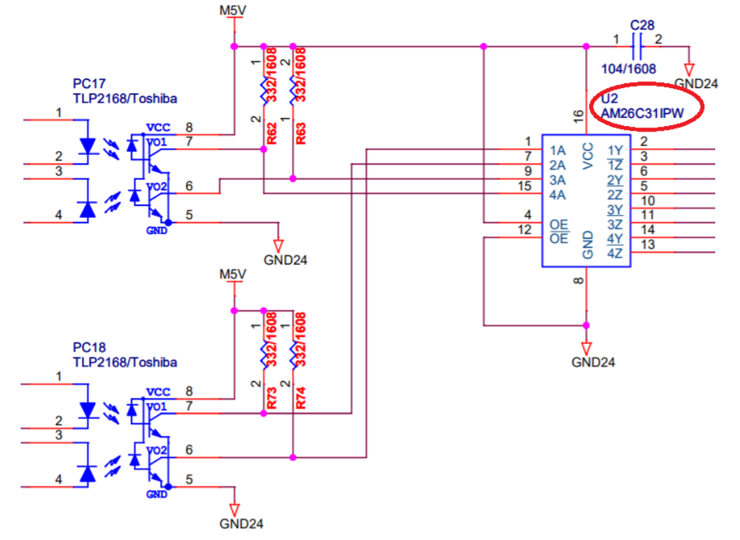
  • The AM26C31 circuit is shown in the figure above.

    The AM26C31 does not produce much heat. When measured with a thermometer, it was measured at an ambient temperature of 20 degrees to about 40 degrees.

    I did not connect anything to the output of the AM26C31 in the AM26C31 Line driver circuit above.

  • Hi Goowoon,

    It sounds like AM26C31 is behaving normally in the circuit above. I don't see an issue with the device pins being driven in this way. 

    Given the information in my previous reply, do you think this explains the temperature increase you are seeing in AM26C32? Would you like further recommendations on how to reduce this heating or is the heating acceptable given this explanation?

    Regards,
    Eric

  • Hello Eric !

    I think the current AM26C31 circuit part is not a big deal. However, I think there is still some problem with the AM26C32 circuit. The current of the photocoupler connected to the AM26C32 receiver is 6mA, but the temperature rises from 45 to 50 degrees. Do you think this is the normal operating range?

    Please let me know if you have any further advice to improve or fix this problem.

  • Hi Goowoon,

    Yes, as this temperature is below the recommended Max ambient temperature range, this temperature should not cause damage to the device. The device is designed to operate at this Max ambient temperature while still dissipating its own power, so the device temperature can increase past the specified ambient Max before damage will occur. 

    The cause of the heating is likely the large current draw from the digital output pins. This coupled with the device's quintessential current draw mean the device will likely have to dissipate over 100mW of power. With the relatively high thermal resistance of TSSOP package, this will translate to an increase of temperature around 10 to 20 C above ambient. This value is above what you may see in other applications because the device's digital outputs are typically not used to drive large current loads. 

    If you wish to reduce the device temperature, either less current needs to be drawn from the device pins or more thermal relief can be provided using a different package type (such as SIOC) or a heat sink. If the device is able to drive the photocoupler without other issue, AM26C32 will be fine to operate at this temperature. The result however would mean the system's operational ambient temperature may need to be closer to the transceiver's Maximum specified limit. 

    Let me know if this makes sense or if you have other concerns. 

    Regards,
    Eric