This thread has been locked.

If you have a related question, please click the "Ask a related question" button in the top right corner. The newly created question will be automatically linked to this question.

DS90UB949A-Q1EVM: How to connect SMA connectors

Part Number: DS90UB949A-Q1EVM
Other Parts Discussed in Thread: DS90UB949-Q1EVM, ALP, USB2ANY

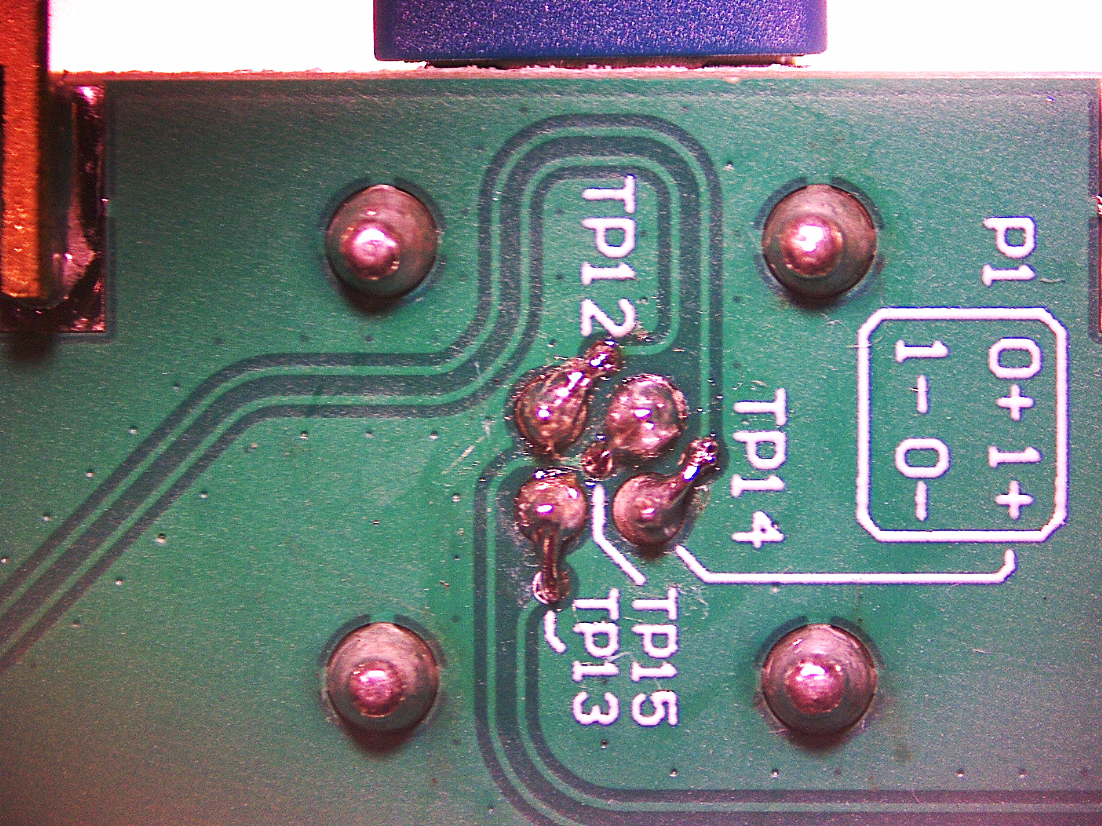
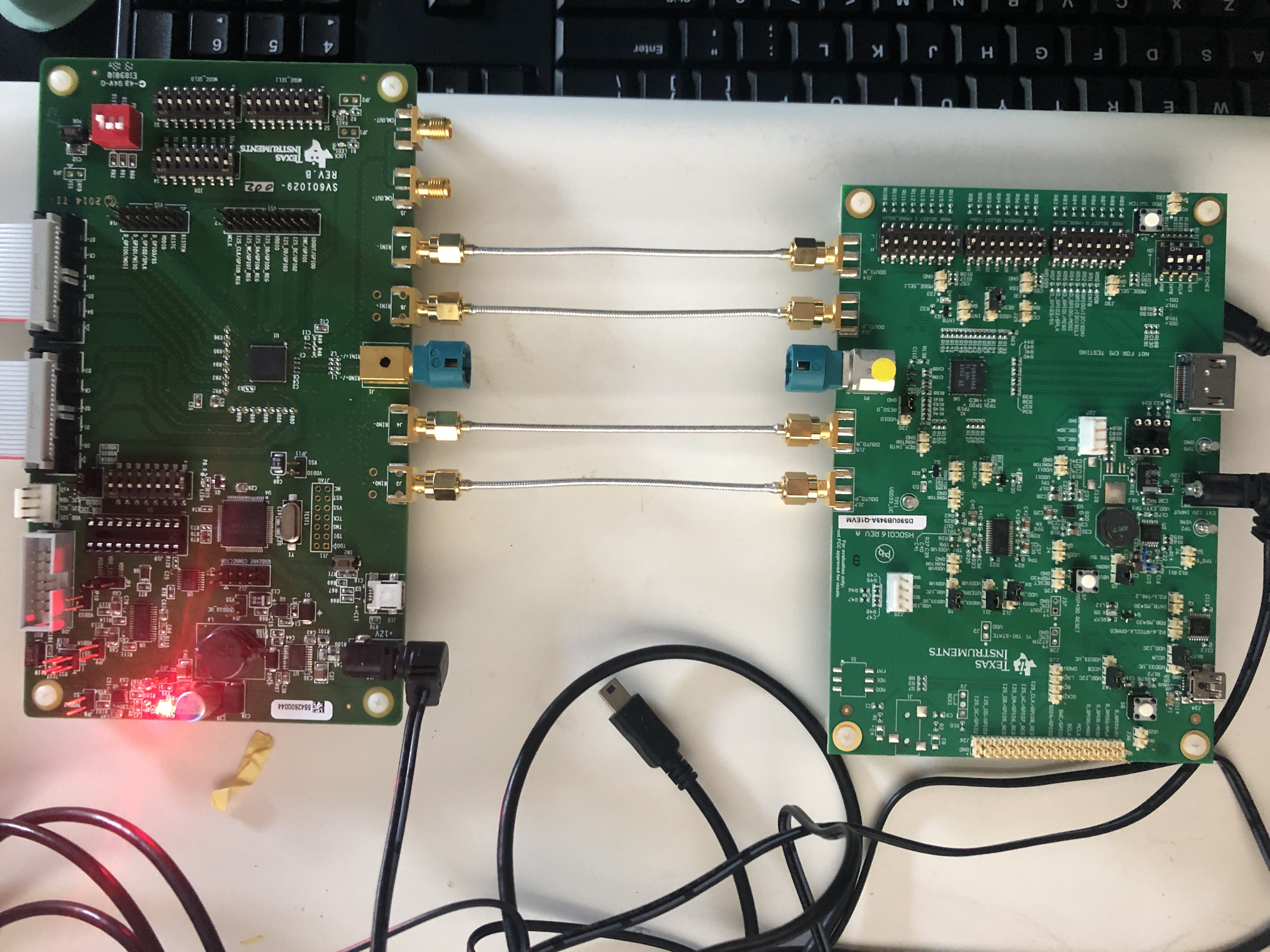
Hi, I have found instructions on how to connect the SMA connectors in this forum for the DS90UB949-Q1EVM, but not for the "949A" variant. It appears on the back-side of the board, next to the P1 FAKRA connector, that there are test-points which could be soldered to with tiny jumper wires. The test-points appear connected to the SMA connectors, so I could use jumper wires to connect them to the corresponding pins on the P1 connector. Is this the intended way of connecting the SMAs? It seems a bit messy and would definitely cause an impedance discontinuity.

On a related note, are there instructions somewhere how to set-up the SerDes connection using unbalanced (rather than differential) coax connections?

  • Hello Alex,

    Yes, your explanation is correct. To connect the SMAs please solder 0 ohm jumper resistors, size 0402 or 0603 on the 4 signals coming from the HSD connector to the SMAs. There will be a small stub going to the HSD connector, but we have tested this connection up to the max supported speed of 949A between EVMs successfully. 

    For setting up coax for 949A, please see datasheet section 8.2.1

    Best Regards,

    Casey 

  • Hi Casey,

    Thanks for your reply. I don't believe that will work for the 949A as it does for the 949, as there is no place to put the resistors, rather just tiny test points next to the HSD connector. In my post I was suggesting using very thin wire, maybe 30 gauge or thinner, to jump from the test points to the HSD connector.

    Please see below for an image of the bottom copper layer artwork, showing the four transmission lines going from the side of the board/SMA connectors to test points next to the HSD connector.

    Best,

    Alex

  • Hello Alex,

    The picture didn't come through but I know what you are talking about. It is best to avoid using wires. What we have done in the past is either to bridge solder directly from the pin to the test pad (since they are quite close), or populate a 0 ohm 0402 resistor between the test pad and the connector pin.

    Best Regards,

    Casey

  • Hi Casey, I ended up using wires about the size of 0402 resistors to form the bridge, so I would assume that's okay. And, I am able to form a reliable connection to the 948 deserializer, up to a point. I am using a custom EDID to set the timing of the HDMI signal that I plug in, and it works up to a pixel clock of 110 MHz. However, somewhere between 110 MHz and 120 MHz, the link to the deserializer becomes inactive-- the "FPD3 Status" section of the HDMI tab in ALP goes from "Link Ready" and "Link Active" both being true to both being false.

    Any idea what's going on here? I need an overall pixel clock of 148.5 MHz, well within the range on the datasheet. I am using Dual FPD3 link mode as well.

    Also, toggling the "BISTEN" switch on the deserializer never gets the PASS LED to light, which I thought it was supposed to. So maybe I don't have a reliable connection, even though ALP says I do? After running for several minutes I only have a couple dozen CRC Errors.

    Best,

    Alex

  • Hello Alex,

    It doesn't really sound like the connection is reliable if you are getting CRC errors and if the link only works up to a certain PCLK point. I am not so sure about the small wires. I highly recommend just bridging the solder directly over or using proper 0 ohm shunts. Are you using single link or dual link between 949A and 940? 

    Best Regards,

    Casey 

  • I'm using dual link. The wires themselves are smaller than the solder bridges--I can try to remove them but the bridges will be about the same size. Here is what it looks like now:

  • Hello Alex,

    I still believe it can be done a little bit more cleanly with 0 ohm jumpers if possible. Like I said, we have done this before successfully up to > 170MHz. 

    Is the same thing being done on the 948 EVM?

    What type of cable and length are you using? Can you share a picture of the full test setup?

    Best Regards,

    Casey 

  • Hi Casey,

    Indeed, I was able to clean it up by using direct solder bridges, and now I can get to 148.5 MHz. I also cleaned up as much residual flux as I could between the solder joints. I've attached a pic below of the updated setup for reference. I am using 3" semi-rigid coax connections. 

    However, I'm still not sure what the correct operating mode should be. Referencing section 8.2.1 of the 949A datasheet it appears that the COAX setting is indeed for single-ended connections. Does that mean with my current set-up, I should have the EVMs operating in STP mode, because I am using the same differential connections that would be used for STP?

    Thanks,

    Alex

  • Hello Alex,

    Good news! For this configuration you are using differential (STP). 

    Best Regards,

    Casey 

  • Hi Casey,

    I am now switching the link over to single-ended and having some issues. I am doing this by setting Switch 3 of MODE_SEL1 to HI on the serializer, and Switch 4 of MODE_SEL1 to HI on the deserializer. I have not yet changed the physical/wiring configuration from what you see in the post above, and I am able to get the LOCK LED to stay solid green at my pixel clock of 148.5 MHz.

    However, if I remove the coax connections for the negative half of each differential pair of the link, and place 50 ohm SMA terminations on the newly disconnected SMA connectors, I cannot get a stable link at 148.5 MHz (or even at lower frequencies). Is the single-ended mode designed to operate at such high frequencies? Or do you have any other ideas about what might be happening? In this configuration, the LOCK LED looks like it is pulsing very fast.

    Best,

    Alex

  • Hello Alex,

    Please confirm that you have added the 50 ohm termination on both the serializer and deserializer sides. Also make sure to adjust the negative side AC coupling capacitor to 47nF as per the recommendations in table 13 in the 949A datasheet for example (applies to both 949A and 948 sides). In single ended configuration the negative side AC coupling cap needs to be half the value of the positive side AC coupling cap to balance the circuit. 

    Best Regards,

    Casey 

  • Yes, I have indeed added the 50 ohm termination on both sides, but have not adjusted the negative side coupling capacitor. I will try that next. Do you have an application note or something you can point me to that would explain how this balances the circuit? I'm curious... Thanks!

  • Hello Alex,

    We do not have an app note but the high level explanation is this: In STP configuration each line has two 100nF caps in series (one at each side of the link) which gives an equivalent total capacitance of ~50nF. So in coax configuration the negative side it terminated locally on each side and there is only one cap looking into the termination. Positive to positive connection still sees equivalent 50nF series capacitance but negative sides see 100nF. Using 47N (closest standard value to 50nF) compensates for this. 

    Best Regards,

    Casey 

  • Makes sense, thanks! I'll report back how things go once I get the caps to try.

  • Hi Casey,

    I tried replacing all negative line caps with 47 nF ones (C106 and C109 on the 949A EVM, and C4 and C7 on the 948 EVM) yet the boards are doing the same thing as before--rapidly flickering link LED, and Analog Launchpad is crashing. I then took a closer look at the 948 EVM datasheet and saw that the positive line caps (C3 and C6) were actually 33 nF ones. So, I replaced those with 100 nF ones. The two boards don't recognize each other at all.

    Would it have been better to go with 33 nF/15 nF on both boards instead? Any other ideas?

    Best,

    Alex

  • Hey Alex,

    I would suggest 100nF and 47nF for DOUT/RX0+ and DOUT/RX1- respectively. So you have 50 ohm terminations also populated on all DOUT/RX negative connections at the SMA connectors of both 949 and 948 and you are using two SMA connections between DOUT0+ -> RX0+ and DOUT1+ to RX1+?

    I believe this should work correctly. You have also made sure to solder the jumpers from the HSD connector to the traces which go out to the SMAs on both sides now? Maybe you could share a couple pictures of the test setup/ board configurations now that you have made changes?

    Best Regards,

    Casey 

  • Hi Casey,

    Yes, I have done all of the above. I've verified that the terminations are 50 ohms and that the capacitors are 100 nF and 47 nF (within tolerances). I've also verified the MODE_SEL1 switches on both boards. Please see photos below.

    Best,

    Alex

    On 949A: C104: original 100 nF cap; C106: modified to 47 nF cap; C108: original 100 nF cap; C109: modified to 47 nF cap

    On 948: All caps have been modified. C3 and C6, 100 nF; C4 and C7, 47 nF.

    All HSD traces have been attached to SMAs:

    949A:

    948:

    Here is the complete setup:

  • Hello Alex,

    Can you please try removing the common mode chokes L4 and L5, then place 0 ohm resistors across the traces to bridge the connection?

    Best Regards,

    Casey 

  • Hi Casey,

    I have done this, and the situation has partially improved (why is that?). For example, with the default EDID loaded at startup, plugging in an HDMI signal to the 949A causes the LOCK LED on the 948 to light solid green. However, in Analog LaunchPad, if I click on the 949A, it still freezes the program, and if I click on the 948, the "Partner Information" oscillates between these two states:

    Best,

    Alex

  • Hello Alex,

    The CMC is meant to block common mode signal fluctuations while maintaining differential mode transmission, but coax configuration is single ended so the CMC needs to be removed. 

    Before moving to using the external HDMI source, can you try the link now with PATGEN from the 949A with internal timing and internal PCLK? Does that work correctly?

    Best Regards,

    Casey 

  • Hi Casey,

    I can't use the PATGEN because accessing the 949A causes the Analog Launchpad software to crash--that's why I had to see if I could get the LINK LED to light with an external HDMI connection.

    Has the 949A-948 EVM combo been tested successfully in the single-ended configuration? If there is indeed a common mode signal, I wonder if this would be affected by the differential trace arrangement on the EVM PCBs, even with proper termination. I would imagine that circuit boards specifically designed for single-ended use would ideally terminate the negative end of the differential pair with the cap and 50 ohm resistor immediately at the IC leads.

    Best,

    Alex

  • Hello Alex,

    These EVMs have been tested with coax configuration. Also ALP has nothing to do with the FPD-Link connector side of the EVM so if ALP is not responding anymore then it seems likely that something else on the board is damaged or shorted where it shouldn't be which is more likely to be the reason things are not linking correctly. 

    Please double check the power rails are at the right voltage and also double check the I2C rails going to the 949A are toggling correctly 

    Best Regards,

    Casey 

  • Hi Casey,

    Here's where I am right now, perhaps you have further ideas:

    • With J5 set to power the EVM board from USB VBUS, I have verified all power rails (5 V, 3.3 V, 1.8 V, 1.1 V) on the 949A
    • When I open Analog Launchpad with just the 949A EVM connected, upon launch it is always recognized as the 948, so I go to USB2ANY/Aardvark setup and select the DS90UB949 profile (there is no 949A profile)
    • Clicking on "DS90UB949" under "Devices" causes both I2C pins to start toggling properly at least at first (State A)
    • Eventually, while monitoring SCL, it goes into a mode of ~ 5.4 MHz, 1.3 Vpp oscillation, at which point ALP crashes (State B)
    • Pressing the MSP430 Reset button on the 949A EVM allows me to go back to State A
    • At this point, nothing except the USB connection is made to the 949A EVM. However, as soon as I connect the two coax cables to the 948 EVM, the SCL line goes to State B
    • Hitting the MSP430 Reset button stops the oscillations of State B, but as soon as I click on DS90UB949 under devices again, the SCL line goes immediately to State B
    • If instead, I use external power on the 949A EVM (set J5 to TPS 5V) without the USB cable connected, then there are no oscillations on SCL. I can plug in an HDMI cable and the LINK LED lights solid green
    • If I reattach the USB cable to try to communicate over USB2ANY, the oscillations restart, and ALP crashes

    If no further ideas about how to get USB2ANY and ALP to work, maybe my best bet is to control the 949A directly over I2C.

    Best,

    Alex

  • Hello Alex,

    I'm sorry but unfortunately I still think based on these symptoms that there may be damage somewhere on the EVM. Considering you have already checked the most obvious spots it may be very difficult to further diagnose this problem but I have not seen such an oscillation before and it seems symptomatic of damage to something on the board - potentially the MSP430, I2C level shifter, or maybe even the 949A unit.

    One last thing I could suggest trying it to jumper the I2C pins from the 949A EVM over to the I2C lines of the 948 EVM (assuming they are set for the same IO level. Then plug your USB into the 948 EVM but when you go to ALP, select 949 instead of 948. This may enable you to bypass the MSP430 or level shifter assuming that maybe the damage is there. 

    Best Regards,

    Casey