This thread has been locked.

If you have a related question, please click the "Ask a related question" button in the top right corner. The newly created question will be automatically linked to this question.

DS90UB953-Q1EVM: Serializer and deserializer are not locked.

Part Number: DS90UB953-Q1EVM
Other Parts Discussed in Thread: ALP

Dear TI,

I am working on a high speed camera interface project, in which I will use a ZCU102 Evaluation Board (https://www.xilinx.com/support/documentation/boards_and_kits/zcu102/ug1182-zcu102-eval-bd.pdf), DS90UB953-Q1EVM and logiFMC-FPD3-934 (https://www.logicbricks.com/Documentation/Datasheets/HW/logiFMC-FPD3-934_hds.pdf). In this project, the serializer sends video data through a coaxial cable to the DS90UB934 deserializer according to the FPD-Link III protocol. In the end, the deserializer sends the data back to the ZCU102.

I have already read the compatibility pdf (SNLA270A) and the related documents to the serializer, deserializer, EVM board etc. many times. I could configure the deserializer locally using the ZCU102 I2C interface. The problem is to reach the serializer from the deserializer using the pass-through function. They are not locked to each other and when I try to read a register value from the serializer, I always get a NACK from the deserializer.

In this state of the project, I do not send data, I only want to configure the serializer using the back channel. In ZCU102, I only use the Zynq Ultrascale+ MPSoC. On the logiFMC-FPD3-934 board, I configure the first deserializer modul, which has an address 0x60 (8 bit) and I use the RIN1 port. On the EVM board, I have made three changes. I put a short circuit to R1, so the serializer gets the 50 MHz oscillator clock. I changed the R12 resistace from 402 to 20k to set the serializer into DVP mode. Finally, I changed the L7 inductor to short circuit, because it was open circuit and the board could not get enough power from the PoC through the R25 resistance (of course I did not have an other inductor). Now the voltage values (PoC voltage, VDD3V3, VDD1V8) are correct.

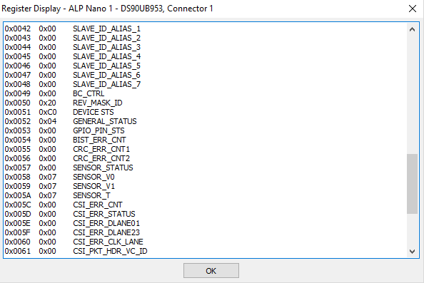
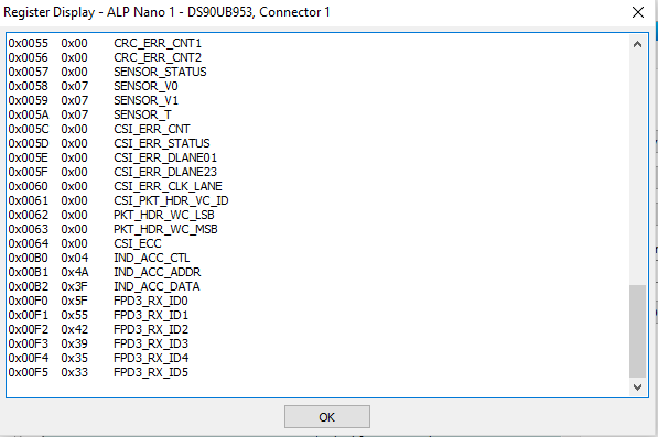
On the software side for I2C read and write, I use the XIicPs_MasterSendPolled and XIicPs_MasterRecvPolled functions from the xiicps driver (https://github.com/Xilinx/embeddedsw/tree/master/XilinxProcessorIPLib/drivers/iicps). I configured the deserializer according to the compatibility document and I added the write permission for RX port 1. I set a serializer alias ID 0x18 which is equal to the serializer ID (I have already tried other values too) and I enabled the pass-through bit (0x58, bit [6]). After this, the SER ID register (0x5B) contains the appropriate ID, but the deserializer and the serializer are not locked to each other. I know it because I read the device status register (address 0x04) and the bit [0] is always 0, so the lock status is always low. I can not find out what should I do or not do to get a high lock status.

If you need more information, I will send it in a reply. It would be nice, If you could help me.

Regards,

Adam Boronyak

  • Hello Adam,

    The issue is most likely with the 953 EVM, specifically the PoC network which is designed for 4G operation, not DVP mode backwards compatibility. I just verified on my own EVMs that if you use the built in PoC network, the forward channel will function but the back channel will not function properly. If you disconnect J15 on the 953 EVM and provide power directly via J19, plus disable the PoC on the 934 side as well then it will work. 

    Also shorting L7 means that you are basically reducing the impedance between the PoC voltage and the signal which is trying to be transmitted so this is not a good idea. DC power doesn't flow through R25 - it goes through L7 and R25 provides damping to the Q factor of the L7 SRF. 

    Please remove J15, power each side locally (no PoC) and you should be able to get this to work. 

    Best Regards,

    Casey 

  • Dear Casey,

    Thank you for your fast reply. I will try your suggestions as soon as I can and inform you about the results.

    Regards,

    Adam

  • Dear Casey,

    Unfortunately nothing changed. The lock status is still low. I have read the port status registers (0x4D and 0x4E) and the values are 0x40 and 0x22, so there is an encoder error and no FPD-Link 3 input clock. What can cause these problems? Are they related to the lock status?

    On the evaluation board, values of L7, C7 and C8 are not correct for my application (L7 is short circuit, C7 is 33 nF instead of 100 nF and C8 is 15 nF instead of 47 nF). Can these differences cause back channel error?

    Regards,

    Adam

  • Hello Adam,

    Are you using PoC or powering each side separately? L7 can not be a short circuit as I mentioned in the previous post so please either depopulate the short or remove J15. 

    Best Regards,

    Casey 

  • Dear Casey,

    I am powering each side separately and also removed J15, but nothing changed.

    Regards,

    Adam

  • Hello Adam,

    Do you have a 934 EVM which you could use to test first before moving to the custom FPGA card? I was able to get this working with the 953 EVM -> 934 EVM using the steps provided. I'm not sure if the issue is related to the custom card

    Best Regards,

    Casey 

  • Dear Casey,

    Unfortunately I do not have a 934 EVM. I reviewed the PCB schematic, but I do not see essential differences between this EVM board and my logicBricks board. Perhaps the VDDIO voltage difference is relevant. In my board, this comes from the ZCU102's VADJ voltage (1.8V) and in the EVM board, this is 3.3V if you place the jumper on pins 1 and 2 for J1. I am not sure if this can cause my problem. An other question: what is the rule of the microcontroller (MSP430F5529IPN) in the EVM board? Can that controller influence the back channel operation?

    Regards,

    Adam

  • Hello Adam,

    VDDIO voltage will not affect the FPD-Link. The microcontroller is just for allowing interface between the I2C control of the device and the USB port when you connect the EVM to the ALP GUI. It does not affect operation of the FPD-Link either. 

    Can you confirm on both sides that the MODE strapping is being correctly recognized by the device? Please check the registers of the 934 and 953 locally to confirm that 953 is being set for DVP mode and 934 is being set to either RAW12HF or RAW10 mode. Also on the 934 please confirm that the cable type is being set for coax by the mode strap pin. 

    Best Regards,

    Casey 

  • Dear Casey,

    I have read the MODE_SEL register (0x03) of the serializer with the ALP software and the value is 0x4D, so it recognized the MODE strapping correctly. On the deserializer side, it is always the default value, 0x7F (port config register, address 0x6D). I have read it so many times during the configuration. The conclusion is that these values are correct for my application. The only thing that strange for me is the reserved clocking mode on the ALP information tab. I attached screenshots about this and the register values. Tomorrow I will try to debug the registers of the serializer with the ALP when they are connected to each other.

    Regards,

    Adam

  • Dear Casey,

    On Friday I configured the serializer with ALP according to the compatibility document and attached it to the deserializer with a coaxial cable but nothing changed. In the information tab, unknown deserializer is written and the serializer is not linked to it. Registers are the same as before. Please can you give me ideas what other things can affect the FPD-Link?

    Regards,

    Adam

  • Hello Adam,

    Can you share the schematics for the 934 card?

    Best Regards,

    Casey 

  • Dear Casey,

    Sorry, but the schematic of the logicBricks board is not public. You can see the differences below. The first value is concerned to the logicBricks board and the second value is concerned to the 934 EMV.

    - VDDIO 1.8V - 3.3V
    - DIfferent capacitors on the voltage pins (except 1.8V FPD0 and FPD1) 10u ... 0.01u  (each decade and 2x0.01u) - 1u ... 0.01u
    - GPIO0, BISTEN, PDB, SEL, OEN, OSS_SEL connected to +Vadj (1.8V) (I can control them if required.)
    - GPIO3 1.8V & 2.2k - 3.3V & 4.7k
    - I2C VDD 1.8V - 3.3V (There is a voltage translator on the logicBricks board.)
    - MODE 10k - 13.3k
    - IDX 10k - 40.2k

    Regards,

    Adam

  • Hello Adam,

    Please adjust the 934 strapping so that BISTEN is LOW. Also, you are saying MODE is pulled to 1.8V with 13.3k? Is there any pulldown resistor on MODE or only pullup?

    Best Regards,

    Casey 

  • Hello Casey,

    Tomorrow I will try to set BISTEN to low. The MODE pin is pulled to 1.8V with 10k.

    Regards,

    Adam

  • Dear Casey,

    Finally, it works. I removed the pullup resistor from BISTEN and now everything is fine. Lock and pass are high and the configuration was successful. Now I can go forward in my project. Thank you very much for your help.

    Regards,

    Adam