This thread has been locked.

If you have a related question, please click the "Ask a related question" button in the top right corner. The newly created question will be automatically linked to this question.

HDMI Voltage level translator

Other Parts Discussed in Thread: TPD12S016

Hi,

Does TI have a HDMI Voltage level translator IC for ac coupled TMDS data channel?

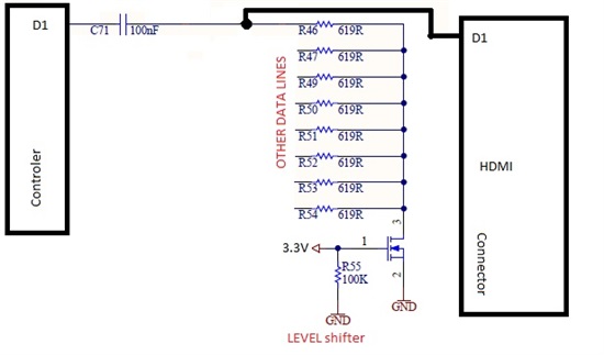
From datasheet "The digital display data signals driven natively through the SoC are AC coupled and needs level shifting to convert the AC coupled signals to the HDMI compliant data signals"

TXP and TXN lines ar on 1V.

DDCCLK, DDCDATA and HPD(inverted logic) are on 1.8V

OR what chip should I use for shifting? I use TPD12S016 for ESD protestion and overcurrent.

Should I post in High Speed Interface Forum?

Best regards

  • Hi,

    Sorry, our team doesn't have the level translator used for AC coupled TMDS signal.

    I can help to move it to the high speed interface forum for checking.

    BR
    junjie

  • Hello ZeroD,

    What exactly are you trying to interface?  Is this an actual video application, custom configuration or LVDS?  TDMS, HDMI and DVI are all compatible.

    Thanks,

  • Hello greenja,

    HDMI

    I have SoC that has AC coupled TMDS data and clock lanes (HDMI Source) and a have to put a level sifter between the Soc and the HDMI connector. What should I put there (IC or discrete level translation), because TPD12S016 has no level translation for TMDS lanes it just has for SDA, SCL and CEC?

    Best regards.

  • Hello ZeroD,

    What SoC are you using?  

    Most chips that are for TMDS (HDMI, DVI) interface do no need any level translation before the connector, in fact none of them do as far as I've seen.  Some manufactures may recommend small resistors in series with the outputs to eliminate any reflection.  If this SoC has the I2C and CEC lines, then you definitely don't need anything between it and the connector.

    Thanks,

  • Hi greenja,

    I'm using Intel atom e38xx.

    greenja said:
    Most chips that are for TMDS (HDMI, DVI) interface do no need any level translation before the connector

    Why? , the lines(TMDS) use power plane  1.0V on SoC, and on connector or sink side is 5V, I'm probably wrong.

    in they schematic they have series resistor with one NMOS and AC coupling capacitors like this:

    http://e2e.ti.com/resized-image.ashx/__size/550x0/__key/communityserver-discussions-components-files/389/3225.hdmi.jpg

    And I want to use TPD12S016 for esd protection and not shore if I need to put the resistors and the NMOS before the TPD12S016.

    Regarding the HPD on TPD120S16 is it inverting or non inverting because the HPD on Soc Is low active and when inactive is 1.8V ?

    And for EMI i think to use common mode choke on TMDS lines , do You have any recommendation ?

    Best Regards.

  • Hello ZeroD,

    I was referring to standard chips for HDMI in general, not SoC devices. I am not familiar with the Atom 38xx, but I do know that they have a program where you can submit you schematic for evaluation. Also, there are open source hardware designs that you can use.

    As for the TPD120S16:

    • 5V Out - a ferrite bead is highly recommended for the 5V HDMI output to the connector. This also supplies power for the i2c pull-ups.
    • Inverted signal - You will have to invert the signal coming from the HPD_A line to the 38xx. You can use a SN74LVC1G14DBVR or similar.
    • TMDS lines - I would say with this setup, you do not need the caps or resistors. You can always include the footprint for both in you design and populate them with 0 ohm resistors. If there are issues with the signal, then you can replace them with the appropriate valued caps and resistors. You do not need any chokes on the TMDS lines.
    • I2C and CEC - these will be pulled up to the 1.8V on the 38xx side
    • EMI protection - that is not my strong point.  I can only say that trace lengths should be as short possible and the same lengths.  Caps as close to the devices as possible also help.

    These are just my recommendations. You can search for design examples specific to the 38xx and submit you design to Intel for evaluation.

    Good luck.

  • Hi greenja,

    Thanks for Your answers. 

    greenja said:
    5V Out - a ferrite bead is highly recommended for the 5V HDMI output to the connector. This also supplies power for the i2c pull-ups.

    I will put one , but have to find right one :)

    greenja said:
    Inverted signal - You will have to invert the signal coming from the HPD_A line to the 38xx. You can use a SN74LVC1G14DBVR or similar

    I'm not shore, if there is no connected HDMI device HPD on connector is low if the VCC= 5V (SN74LVC1G14DBVR), the output of the inverter will be 5V -> to high for Soc HPD what is 1.8V. On other hand if VCC=1.8(SN74LVC1G14DBVR) can I then apply 5V HPD signal from connector to the inverter? Assuming TPD120S16 does't shift voltage level of HPD signal. 

    greenja said:
    TMDS lines - I would say with this setup, you do not need the caps or resistors. You can always include the footprint for both in you design and populate them with 0 ohm resistors. If there are issues with the signal, then you can replace them with the appropriate valued caps and resistors. You do not need any chokes on the TMDS lines.

    Intel recommends to use caps, resistors & nmos network , and for chokes to leave place and if not needed to populate with 0 ohm.

    greenja said:
    I2C and CEC - these will be pulled up to the 1.8V on the 38xx side

    Ok, VCCA of TPD12S016 should be connected to 1.8V 

    Is there problem that the clamps for TMDS refer to VCCA=1.8V because on SoC they refer to 1V?

    greenja said:
    EMI protection - that is not my strong point.  I can only say that trace lengths should be as short possible and the same lengths.  Caps as close to the devices as possible also help.

    Ok , I think the common mode chokes will also help to reduce EMI.

    Best Regards.