This thread has been locked.

If you have a related question, please click the "Ask a related question" button in the top right corner. The newly created question will be automatically linked to this question.

DS90UB914A / 913A Lock LED Blink when Camera data input.

Hi,

1) We are making prototype board board using DS90UB914A & 913A for LVDS interface of Aptina AR0132 & AP0100 with Power over Coaxial.

2) When prototype board of 914A & 913A are power up and connected, the LOCK LED light up and there is 50MHz of Pixclk output at 914A.

3) However, when connect camera with FLASH setting of 10bit of Pixclk = 98MHz, LOCK LED at 914A get blink very fast.

4) After probe on the SCOPE, the data output from 914A are on and off.

5) After checking the design file from TI, there is different of Track width for LVDS single ended compare TI EVAL board Vs prototype board.

A) Prototype board Track width for LVDS are 6mil, however TI EVAL baord are 8mil. What is the correct track width to meet 50ohm?

B) Any Tools that able to measure the line impedance?

C) Need special control of PCB fabrication to meet 50ohm line impedance?

D) Any limit of Track length? Compare of TI Eval board Vs Prototype board, TI Eval board are longer than Prototype board.

Thanks & Regards

KJ LEE

  • Mr Lee
    It sounds like you are having issues maintaining LOCK in your system, this could be due to many things:
    The FPD link signals coming from the DS90UB913A are carrying 1.4Gbps data, and as a result, the traces need to be controlled impedance transmission lines. If the traces are not controlled impedance, then the reflections generated are liable to cause problems with the LOCK. You can measure the impedance of the traces on your board with a Time Domain Reflectometer (TDR).
    So long as the characteristic impedance is a good match to the 50 Ohm coax cable, the trace length will not be a major factor.
    Another possible issue would be the PCLK quality - you can eliminate this by putting the system into BIST mode, and use the built-in clock rather than the PCLK that you are getting from the image sensor - if you see no bit errors with the internal clock, but you do have BIST errors with the PCLK from the AR0132, then you should concentrate on the input clock to the serializer.
  • Hi Mark,

    Do you have any reference Scope that we can looking at for TDR (Time Domain Reflectometry)?

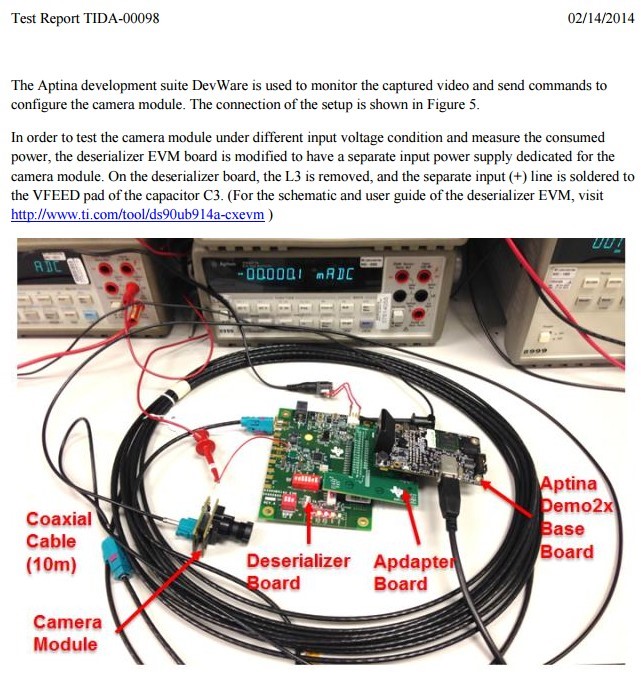
    Besides, I'm looking at instruction notes on the setup procedure & working instruction for demo set of TI EVAL board with Aptina Sensor Module with LVDS as picture below:-

    Thanks & Regards

    KJ LEE

  • Hello KJ
    In our lab, to get the TDR function, we use an Agilent 86100A oscilloscope with a 54754A TDA Module.
    Mark Sauerwald
  • Hello KJ
    I have met the same problem:
    1) We are using DS90UB914A & 913A for LVDS interface with Power over Coaxial.

    2) When board of 914A & 913A are power up and connected, the LOCK LED light up and there is 50MHz of Pixclk output at 914A.

    3) However, when connect camera with FLASH setting of 12bit of Pixclk = 56MHz, LOCK LED at 914A get blink very fast.

    4) After probe on the SCOPE, the data output from 914A are on and off, and the PCLK0 pin on 914A is 56MHz.

    can you tell me where is the problem that led 914A output pin is not the pictrue data ?
    Thank you very much!