This thread has been locked.

If you have a related question, please click the "Ask a related question" button in the top right corner. The newly created question will be automatically linked to this question.

DS110DF111 EEPROM Mode Issue

Other Parts Discussed in Thread: DS110DF111Hi Michael Lu,

I'm using retimer DS110DF111 for my projects. I was success in SMBus slave mode with these configuration

1.Configure VCO for both two channels 0/1 of retimer

· VCO0 is 10.3.125 Gbps ==> register 0x60 = 0x90; 0x61 = 0xb3

· VCO1 is 10 Gbps ==> register 0x62 = 0x00; 0x63 = 0xb2

· PPM deta is maximum ==> register 0x64 = 0xFF

· VCO divide ratio 1/2/4/8 ==> register 0x2f 0x66

2. Configure deemp and VOD for Tx(chanel 0)

· De-emp -3.5dB

· VOD 1000mV

3. Configure Deemp and VOD for Rx(chanel1)

· De-emp -5.6dB

· VOD 1300mV

However I tried this configure with EEPROM mode(SMBus master mode) but It's not work. I was provided the .txt file for EEprom from TI's supporter, I changed it to .bin file and I could program eeprom success by our SMBus controller. After power cycle the board Retimer is in SMBus master mode then it read configuration from EEPROM and put pin DONE# to 0 when it get done , and retimer become to SMBus slave mode but I couldn't write to page register select 0xff.

So, how can I check the status of retimer in eeprom mode after pin DONE# get low. Why I couldn't control retimer when eeprom read done.

This project is so rush, please help me ASAP.

Thank you very much !
  • Hi Ngoc,

    I have opened a new thread for this topic, since it is a different debugging effort from the previous thread it was attached to.

    Regarding your settings, once the DONE# pin asserts low, the DS110DF111 should revert back to SMBus Slave Mode, and you can read the SMBus Slave registers again to verify that the registers were programmed at start as you expected. Can you help with the following?

    1. What do you see when you attempt to access the DS110DF111 after the DONE# pin goes low?

    2. Can you share a file of the the slave mode register dump and the resulting EEPROM .bin file?

    3. Can you describe the specific EEPROM and the EEPROM package type you are using?

    I believe there is a separate e-mail thread addressing this same topic with Triet Tran. Please advise if this is the same case and, if so, whether you prefer we follow up correspondence offline via e-mail or through E2E.

    Thanks,

    Michael
  • Hi Michael,

    1. After pin DONE# goes low. I couldn't access retimer DS110DF111 by write to page register at 0xff==> retimer is still in SMBus master mode, and I couldn't check the status of retimer.

    2. I received two files from TI supporter please shared me your email, I will send them to you.

    3. AT24C04D-SSHM-T-GP is eeprom package we used in our projects.

    One more strange symptom that after I program eeprom and read back and compared it's exactly the same with eeprom file. But after we power cycle the board then read back data from eeprom ==> the first 16bytes is 0x00 , difference with the original data
  • Hi Ngoc,

    Thanks for the information. I will investigate these files and get back to you by the end of this week.

    Regards,

    Michael
  • Hi Michael Lu,

    Thanks for your response, Now we're successful on retimers eeprom mode. The issue is Due to conflicted of SMBUS controller in my projects.

    Thanks..

  • Hi Ngoc,

    Thanks for following up on this issue to help close it out. If you run into future issues, please feel free to reach out to us again.

    Regards,

    Michael
  • Hi Michael,

    I got another issue with Retimer EEPROM mode. Please help to review if you got any experience on this issue yet.

    In three test cases below, we use the same Retimer's parameter for both two channels as the previous comment above.

    1. With SMBus slave mode :  I init Retimer after our 10G interface initialization ==> with this configuration 10G interface is work stable over 1000 times power cycle the board.

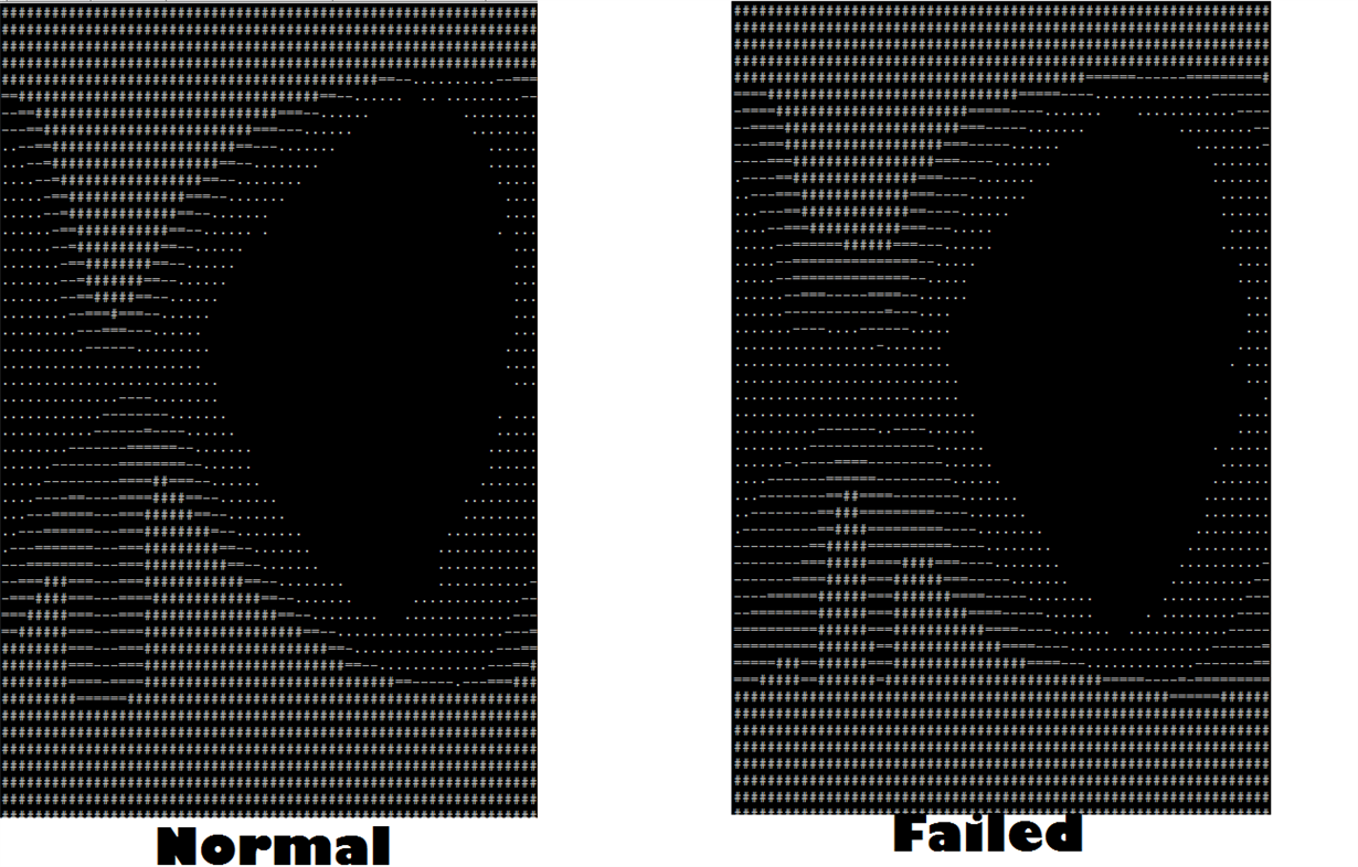
    2. I Configured retimer in eeprom mode ==> retimer is init when board is powered up, then we init our 10G interface after==> This configure is not stable we got many " retry time out" and "UDP wrong check sum" when put/get file 50M to server( the error rate is 1/246), after that I use our SMBus controller reset CDR of retimer, and I can put/get file normally. We got  the attachment as  retimer's eye compare image in two case success and unsuccessful.

    3. I also tried SMbus slave mode but we init Retimer DS110DF111 before we init our 10G interface. The status is the same with test case [2].

    So, I assume that If we init Retimer DS110DF111 before 10G interface, CDR/DFE of retimer will lock the bad 10G signal so the output signal is bad too.

    Our goal is use retimer in Eeprom mode  without any more CDR reset command and work stable as test case [1]. Please give me your advise to improve CDR/CTLE/DFE adaption in case it's inited before 10G interface. Or any way to move the initialization after 10G interface in eeprom mode.


    Thank you very much!!

    Ngoc

  • Hi Ngoc,

    It appears that the DS110DF111 is over-equalizing the signal when configured with the EEPROM and initialized before the 10G interface.

    For the "Normal" and "Failed" cases what are the register values for Channel Register 0x52?  It may be possible to constrain the allowed CTLE adaption process or table to keep the interface at a better equalization solution.

    Regards,

    Lee