This thread has been locked.

If you have a related question, please click the "Ask a related question" button in the top right corner. The newly created question will be automatically linked to this question.

DS100DF410 tuning procedure

Other Parts Discussed in Thread: DS100DF410, USB2ANY

Hi all,

Currently we are trying to tune DS100DF410 retimers. We are using the internal PRBS pattern generators and Eye Opening Monitors. Using a QSFP loopback module we are sending the bit patterns from retimer 1 to retimer 2. It is very hard to tune the retimers since many settings can be changed. Is there a sort of tuning procedure available?


Thanks.

  • Hi,

    We don't currently have a tuning script for DS100DF410. But it is not as complex at it seems.

    • On the Rx side there is not much if any tuning needed by the host. Specifically the Rx EQ on the DS100DF410 is adaptive. The only setting to decide is the adapt mode i.e. whether to use adapt 1 vs 2
      • For channels with loss < 30 dB, and with no major crosstalk or reflection issues adapt mode 1 is suitable. This mode uses CTLE only
      • For loss > 30 dB and or with significant crosstalk and/or reflections we recommend adapt mode 2. This mode uses CTLE plus DFE on Rx
    • For Tx side the DS100DF410 implements a simple de-emphasis driver, which allows for compensation of up to 12 dB of insertion loss. My general guidance for Tx is the following:
    • Target VOD in order of 0.8 to 1Vpp for backplane application, and 600-800mVpp for port-side/optical module
    • If Rx EQ on other side is not available and/or insufficient then set the Tx de-emphasis to value corresponding to amount of insertion loss compensation desired
    • If sufficient Rx EQ is available on the other side I would recommend targeting zero Tx de-emphasis on the DS100DF410. The DS100DF410 datasheet has a table illustrating compensation (in dB) as a funciton of Tx de-emphasis setting
    • You may sweep Rx BER or eye opening as a function of DS100DF410 de-emphasis for a fixed VOD value if you want to ensure optimal de-emphasis setting

    Hope this helps.

    Cordially,

    Rodrigo Natal

    DPS Applications Engineer 

  • Hi Rodrigo,


    Thanks for the quick reply!

    Okay, so when I've chosen Adaptive Mode 2, it uses both DFE and CTLE. What about these settings? Much settings (DFE TAP1-5, CTLE boost settings, etc.) can be changed.

    One retimer is between CPU and QSFP+-cage (Tx) and one retimer between QSFP+-cage and CPU (Rx). I think estimating the losses is very hard. Do I need to try all the different de-emphasis settings then?

    What do you mean by sweeping the Rx BER? Is it possible with the SigCon architect software?

    Thank you in advance!


    Kind regards,

    Sjors

  • Hi Sjors,

    Rodrigo is out of the office for the rest of this week and will be returning on Tuesday (May 31). In the meantime, I will do my best to answer your questions.

    1. Adapt Mode 1 uses CTLE only. Adapt Mode 2 is a mixture between CTLE adaptation and DFE adaptation. The DS100DF410 first adapts the CTLE for optimal settings, then it tunes the DFE while keeping the CTLE settings tuned at its optimal setting. After the optimal DFE is found, the CTLE settings will be tuned one more time in case a new optimal CTLE setting is found when used with the newly tuned DFE. All of this tuning occurs automatically. If you wish to change the CTLE or DFE settings by implementing settings of your own, you will need to override the automatic settings manually.

    2. If you know the approximate distance in inches or mm from retimer Tx to QSFP+ cage (for Tx direction) and retimer Tx to CPU (for Rx direction) as well as the dielectric material (for example, Megtron-6 or FR-4), then we can make a rough estimate as to how much loss we anticipate. However, there is no harm in sweeping through all the de-emphasis settings available to find the optimal setting for your system. First start with zero de-emphasis and slowly increase. It is more common to see low de-emphasis settings than high ones, unless there is a very long distance (10-15+ inches) from retimer Tx to QSFP+ cage. The same is true for the other direction (retimer Tx to CPU).

    3. By sweeping the Rx (CPU on the other side of the QSFP+ cage after the DS100DF410 Tx) BER, I believe Rodrigo means for you to keep VOD constant and then cycle through each de-emphasis setting. When you run each test, have the CPU Rx monitor for bit errors and determine whether there is a range of good DS100DF410 de-emphasis settings where there are no bit errors. From this range, you can select the optimal de-emphasis setting for the DS100DF410 such that the CPU receives no errors. You will only be able to program the DS100DF410 with SigCon Architect. The Rx BER will need to be measured by programmable access to the CPU you are using.

    Michael
  • Dear Michael,

    Thanks for your reply.

    Sorry for my delayed reply. Some other work needed to be done. I think I will come back to you this monday.

    Thank you.

  • Hi Michael/Rodrigo,

    I managed to acquire locks when enabling the PRBS pattern generator on the first retimer which is connected to the second retimer using a QSFP loopback adapter. This takes several minutes. What time it should take approximately? I think several minutes is very long.

    Thank you.

  • Hi there. CDR lock aquisition should take 100ms or less, if the CDR is configured to the default reference mode value of 3. The reference mode is set using channel register 0x36[5:4].

    Regards,

    Rodrigo Natal

    DPS Applications Engineer

  • Hi Rodrigo,

    Thanks for your reply. On our receiving retimer, reference mode 3 is enabled (reg. value 0x31). Nevertheless it takes some minutes to acquire a lock. Could you please advise me about the settings I need to check to get the lock time as it should be (< 100ms)?

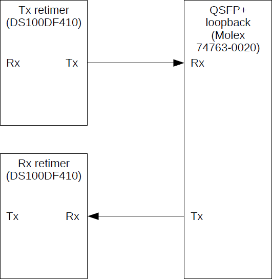
    For now, the setup I am using is like shown in the figure below. The left side of the block diagram is left floating/not connected.

    I don't know if it worked, but I also tried to attach the configuration files I am writing to the retimer registers. Please let me know if you can't open these.

    read_tx.cfg
    read_rx.cfg

    Thank you in advance.

  • What is the methodolyg being used for measuring the lock time? Note that polling the value of the CDR lock status bit is not an accurate way to measure lock time, particularly if you are using the TI SigCon Architect GUI.

    Thanks,

    Rodrigo Natal

    DPS Applicaitons Engineer

  • I am reading these lock indication bits (register 0x02, bit[3]) using software. We developed a custom software application to monitor and configure the retimers using the USB2ANY dongle. Sometimes I am using the SigCon software as well. There are no lock indication LEDs on the PCB.

    I really think something is wrong with the configuration (or setup?). Sometimes it takes worst case about 30mins to acquire a lock on a certain channel. What I expect is that after programming the retimers, using for example the SigCon software, the retimers will instantly lock or not lock at all. Not that is takes ages.

    Thanks.

  • Hi Sjors. Brainstorming this, one possible issue that might be happening is over-equalization preventing the CDR from locking. To work around this, you can try setting the retimer channel to adapt mode 0 and forcing CTLE boost setting of 0. See the routine below:

    REG

    Value

    Comment

    0x31

    0x00

    Set Adapt mode 0

    0x2D

    0x88

    Enable EQ override

    0x03

    0x00

    Set EQ = 00

    0x3A

    0x00

    Set EQ = 00

    0x0A

    0x1C

    Puts the CDR into RESET

    0x0A

    0x10

    Releases the CDR from reset

    Cordially,

    Rodrigo Natal

    DPS Applications Engineer

  • Hi Rodrigo,

    Thanks for your reply.

    I changed the settings like you described in the table, but it seems this even makes it worse... I think something else is still wrong.

    Kind regards,

    Sjors

  • Hi Sjors. My apologies as I don't recall some of the details for your setup. For the Retimer channel whose Tx electrical output goes to the QSFP+ electrical input,

    • What is the retimer Rx input data you are using, or are you running retimer in VCO free run mode? 
    • Also, does the retimer have REF_CLK signal?

    Regards,

    Rodrigo 

  • Hi Rodrigo,

    • At the moment, the transmitting retimer does not have an input signals on its Rx pins. I configured the signal detect to 'Force Enabled' and enabled the PRBS pattern generator.
    • I am using a 25MHz clock generator (CTS 632N3I025M00000) to generate the REFCLK signal. The clock generator is connected to the Rx retimer. The REFCLK_OUT pin from this retimer is connected to the Tx retimer REFCLK_IN input. So: Clock generator -> Rx retimer -> Tx retimer.

    Actually I'm not sure if the VCO is in free running mode, but according the datasheet:

    If there is no signal, the VCO clock will be free-running. Its frequency will depend upon the divider and CAP DAC
    settings and it will vary from part to part and over temperature.

    Register 0x08 is set to 0x0C, register 0x09 is set to 0xEC.

    Hopefully this helps you a bit.

    Kind regards,

    Sjors