This thread has been locked.

If you have a related question, please click the "Ask a related question" button in the top right corner. The newly created question will be automatically linked to this question.

SI test fail for the SFP+ Ports through the Retimer DS100DF410

Other Parts Discussed in Thread: DS100DF410

Dear Sir,

I have a project which uses the SFI Retimer DS100DF410 to output 16x SFP+ Port.  But, with the initial retimer configuration, the SI test result of the 16x SFP+ Ports are all failed.  The fail phenomenon are descripled as blow:

A. The 8180 Pattern is wrong.

B. The PRBS9 Pattern is fail.

C. Just PRBS31 Pattern is pass. 

So, Is this SI fail caused by the initial retimer configuration ?  If yes, why the 8180 pattern is wrong ? Thank you very much !

  • Hi,

    The 8180 pattern is a simple 8-UI square wave.  Have you looked at the result on an oscilloscope?

    Without any single bit transitions this test pattern will be interpreted as a 1.289 (10.3125/8) Gbps pattern.  To lock to this pattern you will have to change the DS100DF410 Channel Register 0x0C value.  Default = 08'h, Change to = 00'h.

    If the attenuation in your system is not high I would also change the value in Channel Register 0x3A. Default = A5'h, Change to = 00'h.

    Regards,

    Lee

  • Hi Lee,

    I'm sorry for reply late.  For me, this is the first time to use E2E and it takes me some time to familiar with how to use it.

    Thanks for your answer.  I still have some questions.

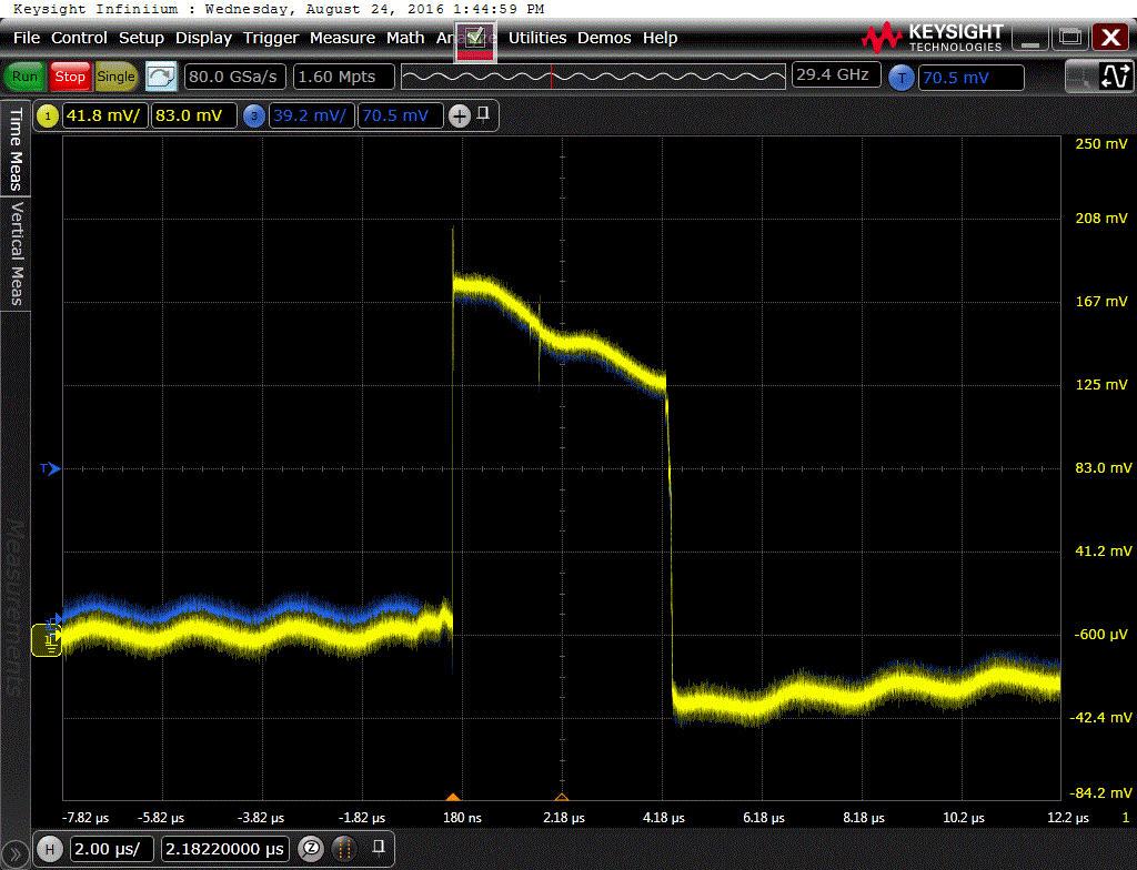
    1. For 8180. I have checked the register 0x0C, the initial value is already 00'h. But the waveform captured by oscilloscope is as below. It’s really strange. So, waht else shoud i do to improve this? By the way, the SFP+ port function test is ok. no problem.


    2. For PRBS9, should i set the Channel Register 0x0C value as "Default = 08'h" or "Change to = 00'h" ?  Now, with the initial setting (0x0C = 00'h) on my board, the PRBS9 fail report as blow. It's the DDPWS item fail.

  • Hi,

    I have never seen a waveform of that rate on an SFP+ interface.  Can you take a picture or draw a block diagram of your setup.  According to the horizontal timebase the high portion is over 4 microseconds in duration.

    Lee

  • Hi Lee,

    Do you mean the 8180 Pattern test setup about the Oscilloscope ? This SI test  in the charge of my SI team colleague in TaiPei. So i can't get related picture. But, i'm sure the Oscilloscope setup is right. Because, there are also another 20 SFP+ ports from the same Switch Chip, the only difference is they are connected to Switch chip dirrectly, don't through the Retimer DS100DF410. And, the 20 SFP+ Ports SI test result are all pass.  

    About the 8180, do you think whether there are some other settings are wrong ?  Because, for the initial configuration i got for my board. the channel register 0x0C default value is 00'h, it's not 08'h as you told before.

    How about the PRBS9? Should I  set the channel register 0x0C as 08'h when test PRBS9 & PRBS31 ?

    Thank you !


  • I would like to understand how the DS100DF410 is connected in the system.  If you can send a schematic it would be helpful.

    Does the setup look like this?

    System -> DS100DF410 -> SPF+  -> oscilloscope ?

    I would also like to see a register dump for all the DS100DF410 registers, this is useful for trying to debug the setup.

    Thanks and Regards,

    Lee

  • Hi Lee,

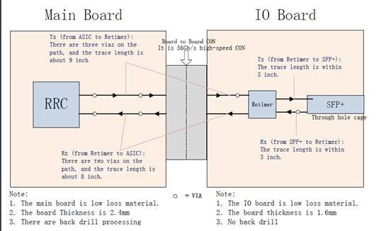
    Please refer to the following block diagram about how the DS100DF410 is coonected in our board. And i hope it would be helpful. (I don't know how to send a attchment via the E2E, ).  


    About the setup, yes, it is :  System -> DS100DF410 -> SPF+  -> oscilloscope

    Thank you that you will check all the retimer registers to help on our case, and i'm looking forward to your new comments.

    At the same time, we are also working on this bug, if there is any findings, i will update to you ASAP.

    Thank you!

  • Hi,

    If you could copy the register download to E2E that would be good enough to read through them.

    Just checking.  Are the connections between the RRC and retimer AC coupled?  Is your oscilloscope AC coupled to the retimer outputs?

    Regards,

    Lee 

  • Hi Lee,

    Thanks for your great support..

    For the 8180 abnormal waveform, maybe we have found the reason: As i told you before, the initial channel register 0x0C value = 00'h. So, when the 8180 pattern is abnormal with the initial configuration, I just re-write the register ="00'h", and as the feedback to you, the waveform is still abnormal.  But, when I try to write the register ="08'h" first, and then write it ="00'h" again, then, the 8180 pattern can be generated normally. and the test result is pass on one port. (Another ports will be arranged to test tomorrow ).

    So, for this phenomenon, can you explain it ? It seams the direct setting 00'h is not valid, but the value is indeed read as 00'h.

  • Since the 8180 signal has no single bit transitions, the DS100DF410 will not lock to this pattern by default.  Removing the signal bit transition check and restarting the DS100DF410's attempt to lock should result in a lock condition and an 8T clock pattern at the output.

    Regards,

    Lee

  • Thanks for your detailed explaination !
  • Lee,

    We were having an issue unlocking the CDR due to certain types os 1G packets and the modification of Channel Register 0x0C value. Default = 08'h, Change to = 00'h. resolved the issue. Can you explain what is the consequence of using this bit change in final firmware ? Is it recommendable to use it in 10G system also ?
  • Sergio,

    This register bit enables or disables the "single bit transition" check for declaring CDR lock.  When this bit is enabled, the internal state machine must record a certain number of "single bit transitions" for a valid lock condition.  The 8180 pattern would not meet this condition since there are no 101 or 010 pattern changes. 

    I would recommend keeping this bit enabled for normal operation.

    Regards,

    Lee

  • Lee,


    Our Design have SFP+ ports connected to the DS100DF410, this SFP+ ports can work either in 10.3125G (66/64) 10Gbase-X or 1.25G (8B10B) 1000Base-X, 10G works OK, what happens is that we findout using valid ethernet packets a certain sequence of packets that makes the CDR to unlock. I can wireshark the packets if you want. We tested in our system and with your development kit and both cenarios the CDR unlock after sending that packet sequence. But we figure out that modifying this register as you recommended to this 8180 issue makes the traffic pass normally.

    As we were having issues in 1.25G (8B10B) do you recommend to change the bit  or do you think it is better to send you the packets and work a little bit more to better evaluate what is happening ? Until now we do not observe no collateral problem after changing this bit for 1.25G traffic.


    Thanks


    Sérgio

  • Hi Sergio,

    There is no problem with setting this bit.  You can try making the change below as well. 

    If you change the equalization value in channel register 0x3A from A5'h to 00'h does the retimer still lose lock?

    The value of A5'h is quite large and usually not needed for low speed applications.

    Regards,

    Lee