This thread has been locked.

If you have a related question, please click the "Ask a related question" button in the top right corner. The newly created question will be automatically linked to this question.

LMH0346 output eye diagrams jitter become more larger

Other Parts Discussed in Thread: LMH0346, LMH0344

Hello,

sorry to trouble you to check my design.

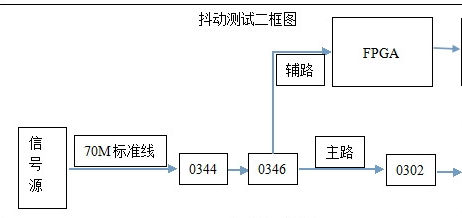
We are using LMH0346 to reclock outpout to improve SDI signal quality. but there is something wrong with that.

The eye diagrams jitter through  LMH0346 is more lager than bypass LMH0346, Please help to check the reason, thanks for your help.

  • Hi Leo,

    I have some questions to help me understand the issue here.

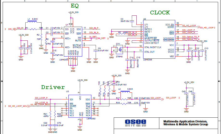
    1. Is it possible to see the schematic for this board and the measurement of jitter you are seeing when the reclocker is active and when the reclocker is bypassed?

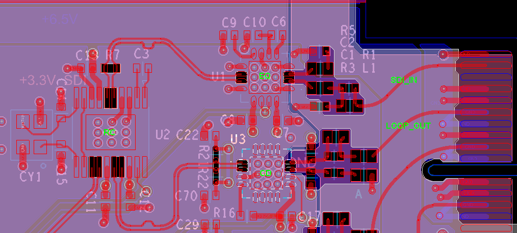
    2. The image of the layout you have shown seems reasonable as faras the reclocker is concerned, with cut-outs on the high-speed pins and closely-coupled traces. When you bypass the reclocker, are you simply forcing the Bypass function by pulling the Bypass Pin up on the LMH0346, or are you modifying the board so that the signal does not route through the LMH0346?

    Thanks,

    Michael
  • Hi Michael,
        Thanks for your help.
        The schematic is as below,  but the photo of jitter measurement is unable to provide temporarily due to no saving during
    experiment.
         But there's a point we just found, We are using  the parameters  of the  Crystal , that the drive level is 10uW, maximum 100uW and shunt capacitance 3pF, But the datasheet says that Recommended Drive Level is 100 μW ,maximum 500uW and shunt capacitance 7pF.
        May there be the reason caused by the crystal parameters differences?

        In addition ,  We are just simply forcing the Bypass function by pulling the Bypass Pin up on the LMH0346 When  bypassing the reclocker.


       Thanks so much!

  • Hi Leo,

    Reviewed your schematic and PCB layout. Please note the following comments:

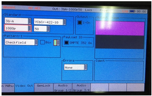
    1). I noticed you are using checkerfiled pattern. Do you see a similar issue when using color bar instead?

    2). C3 Loop filter capacitor layout is very critical. I noticed in your layout, LMH0344 output comes close to C3. When running this test, can you touch with your finger C3 to see if jitter gets reduced?

    3). On LMH0346 power supply pins you are using very small power supply decoupling capacitors. Can you please use one 10uF Capacitor instead of one of these 0.01uF capacitor. Does this reduce the jitter?

    4). It is a good idea to change the crystal to the recommended crystal. But i don't think this could be the cause of this problem since device is locked(this is because you have output waveform). If crystal was the root cause i was expecting LMH0346 to go in or out of lock. 

    Regards,,nasser

  • Hi Nasser,
    Thanks for your suggestion, We'll perform a test ASAP according to your methods.
    But sorry, I can not very understand the terms "checkerfiled pattern" and "color bar" , would you please explain it for me? thanks very much!

    Regards , Leo
  • Hi Leo,

    Looks like there was a typo in the previous post. The term "checkfield pattern" refers to the pattern you showed in your attached photo. The top half of the test pattern is the EQ pathological pattern (magenta color), and the lower half is the PLL pathological pattern (gray color).

    By "color bar," we are referring to the standard SMPTE RP 219 and looks similar to the image below:

    Nearly all video source generators are able to output this standard test pattern.

    Thanks,

    Michael

  • Hi Michael,
    OK, Got it, Thank you very much!

    Regards , Leo
  • Hi Nasser,

         We have already done some  test according your advices.

    1) It indeed becomes better when we are using color bar instead of checkerfiled pattern .

    2) There is no change for the jitter  touching C3 with finger.

    3) It still no better using 10uF Capacitor instead of 0.01uF.

       So , the problem is still existence, any suggestions again? thank you very much!

    Best regards , Leo.

  • Hi Leo,

    I should have noticed this earlier but i just realized you are using 0.47uF for LMH0344 C6 and C10. For LMH0344, we need to use 1uF for C6 and there is no need and you can de-populate C10. Could you please make this change and let us know if you still see high jitter in normal vs bypass mode?

    Regards,,nasser