This thread has been locked.

If you have a related question, please click the "Ask a related question" button in the top right corner. The newly created question will be automatically linked to this question.

DS90UB927/DS90UB928 - Supported pixel clock

Hello Team,

My customer uses the DS90UB927/DS90UB928  pair to transfer FPD Link III data at a pixel clock of 74MHz. Datasheet mentions 85MHz pixelclock support, but they only get a stable link with upto 42.5MHz clock. The Fig 12 in the datasheet shows typical characteristics with 78MHz clock. As 42.5MHz is exactly half of 85MHz I thought if there was any misinterpretation on the measurements.

Test results:

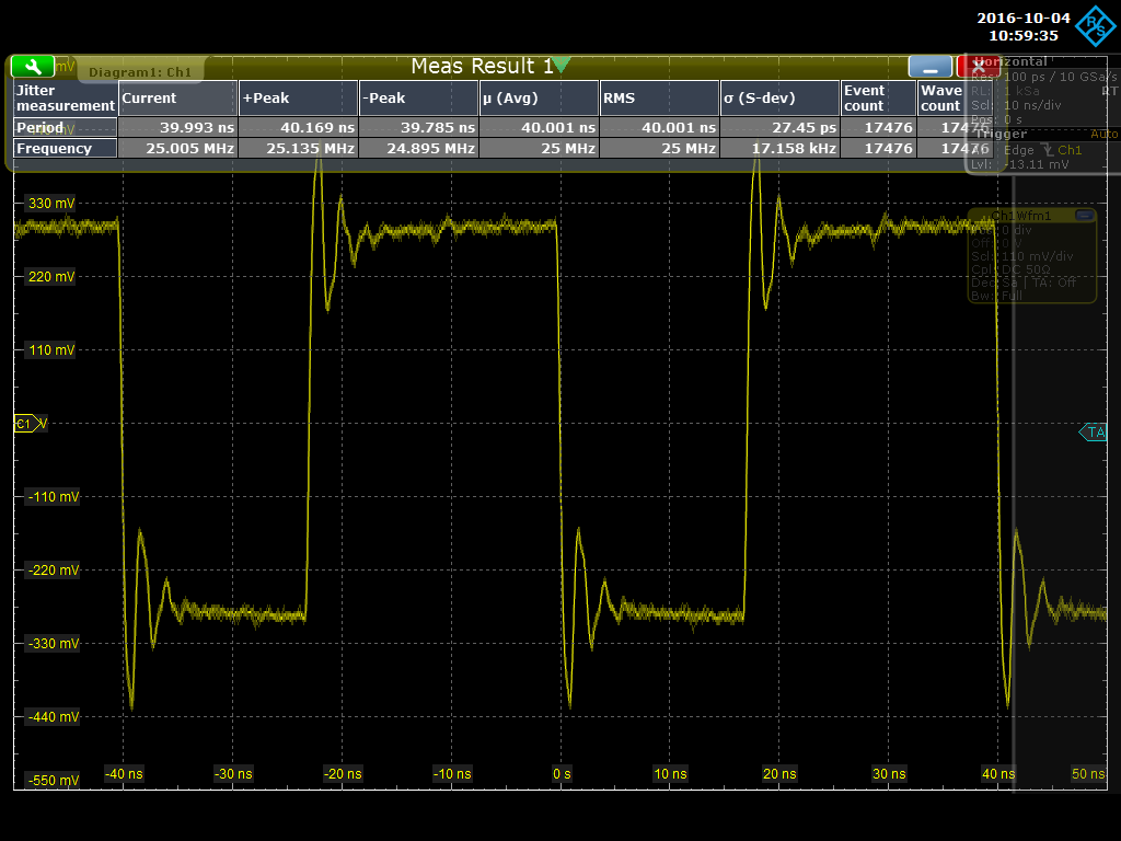
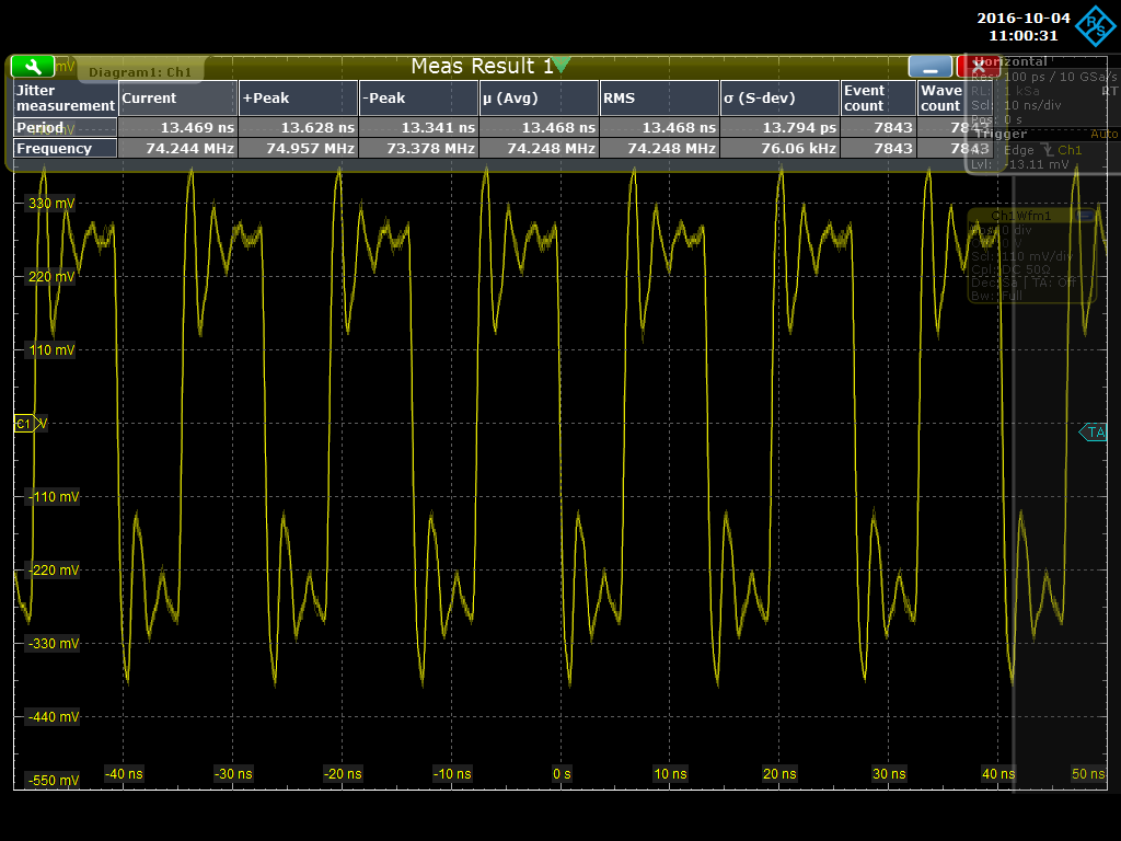
On both the ‘928q-q1 and the ‘927q-q1 the LFMODE = 0 (GND). A measurement of the differential input PCLK can be seen in the attached pictures. As example we have chosen 25MHz and 74.25MHz. With 25MHz the link is constant, with 74.25MHz there isn’t a link. The border we’ve mentioned is 42.5MHz, frequencies below were working fine, with bigger frequencies on PCLK no link becomes ready.

Question:

In addition to  LFMODE=0 , which sets device to support 15MHz to 85MHz pixel clock, are there other options which must be set to operate at higher frequencies?

Thanks and regards,

Mizaur, EMEA Central Apps

  • Team,

    Can we expect an answer soon? Customer sent several reminders already.

    Best regards,
    Mizanur
  • Friendly reminder.

    Customer is waiting for more than 2 weeks now.

    Best regards,
    Mizaur
  • Hi Mizanur,

    There are two main areas that I would recommend to check in this case - the input PCLK signal integrity, and the FPD-Link III channel characteristics.

    The PCLK input has a lot of ringing, so it may be that the 927 is having trouble detecting a stable frequency. Have them repeatedly poll 0x0C to see whether bit 2, PCLK detect, is toggling. Also check to make sure there is 100 Ohm termination on each input OLDI pair.

    What length / type of cable are they using, and have they measured S-parameters to see if it meets our recommendations? There is an NDA-only document explaining the characteristics that our devices expect (I can send you over email if we have an NDA in place with the customer).

    Are these customer developed boards or EVM's? If it is EVM's, make sure they remove the resistors for the pathway they aren't using (for example, if they aren't using SMA connectors, they will appear as stubs unless you remove the series resistors connecting them to the main FPD-Link III trace). If it's customer boards, check the layout to see if the FPD-Link III high-speed traces look okay or if they are particularly long, or have many vias, etc.

    It's also always a good idea to get the schematic to make sure they're not doing anything obviously wrong. Compare it with the datasheet typical connection diagram and ask us about anything unusual.

    Thanks,
    Jason
  • Hi Jason,

    I've checked the 0x0c bit 2. It is not toggeling!

    100Ohm termination are installed in every LVDS lane.

    We are using very high quality cable, e.g.: Rosenberger LD5-104-

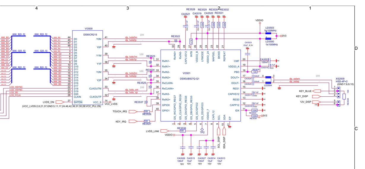
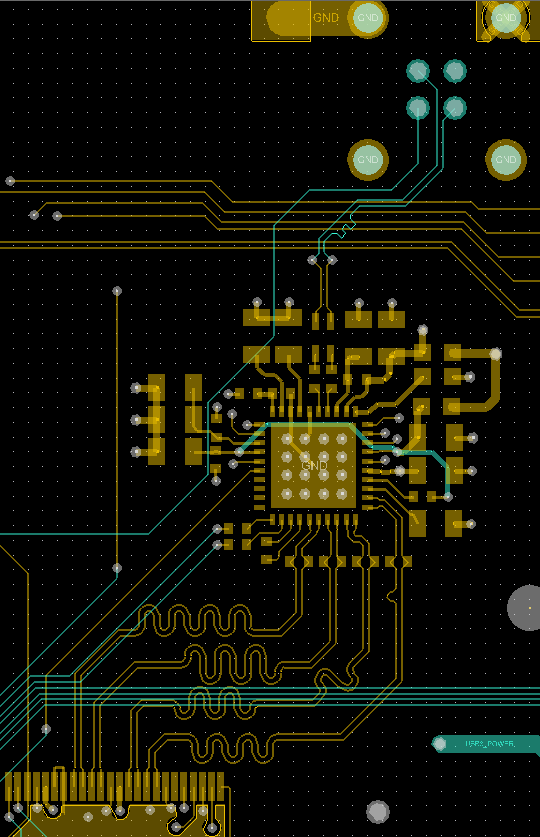
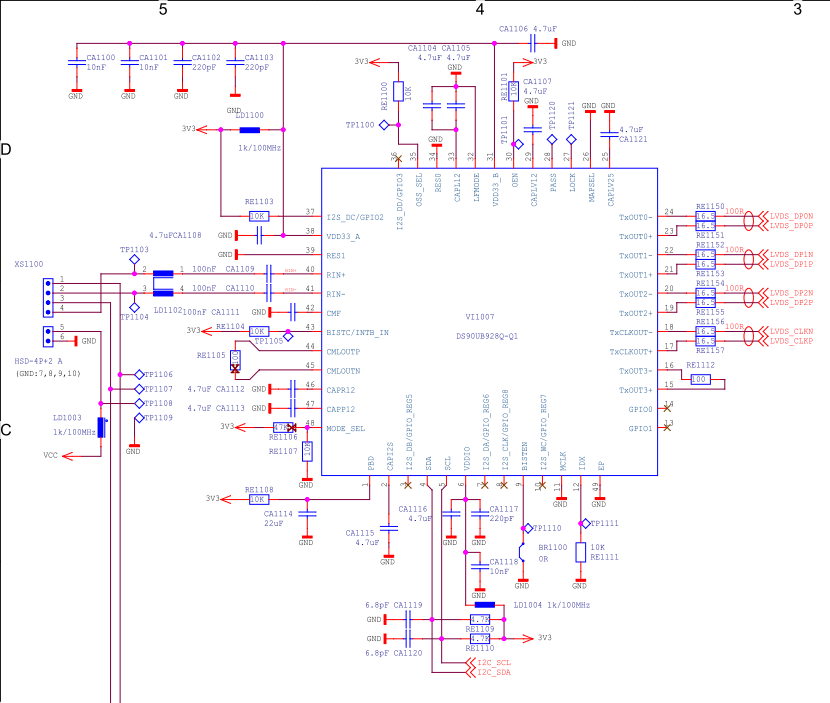
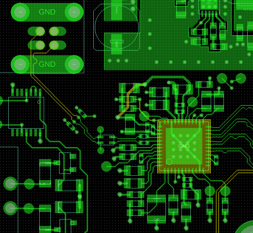
    For chehcking Layout and Schematic:

    This is the serializer side:

    This is the deserializer side:

    Thanks for help.

    kind regards

    Max

  • Is it possible to get an answer?

    Kind regards

    Max
  • Are there some new ideas in the new year?

    I still hope for some help.

    kind regards

    Max