This thread has been locked.

If you have a related question, please click the "Ask a related question" button in the top right corner. The newly created question will be automatically linked to this question.

DS92LX1622, receive signal quality

Other Parts Discussed in Thread: DS92LX1622, DS92LX1621

Dear Specialists,

My customer is considering DS92LX1621 and DS92LX1622. 

Please advise me on questions bellows related to DS92LX1622.

Q1. Can you let me know how to access the input signal quality on DS92LX1622 high speed input? 

Q2. Referring the DS92LX1622 datasheet, the minimum input  amplitude on the high speed input is

+/-90mV (180mV p-p differential) and input jitter tolerance is 0.54 UI typ.

In the meantime, the datasheet insists that the device support up to 10m STP cable transfer.

The ISI case by 10m STP may make further eye distortion.

Don’t you think there are contradict each other? 

Q3. Are there any way to reflect the effect of the on chip equalizer to the eye monitoring?

Q4. One option may be provide the equalizer model to the customer and integrate such model 

into a state of  art oscilloscope, and compensate the monitored eye.

Is it feasible?

Q5. When you monitor the eye quality, you need information on the receiver PLL such as bandwidth

       PLL type etc. Can you provide us such information?

I appreciate your great help.

Best regards,

Shinichi

  • Dear All

    How is the situation?

    My customer wants to know the answer to the questions.

    Could you please advise?

    I am looking forward to your response.

    Best regards,
    Shinichi
  • Hi Shinichi-san,

    My apologies for the delayed response. We are currently returning from the US Thanksgiving holiday, so we were not able to look into your request until today. I will get back to you in the next 1-2 days with a response.

    Regards,

    Michael
  • Dear Michael

    Thank you for your reply.

    I am looking forward to your answer tomorrow.

    I appreciate your great help.

    Best regards,

    Shinichi

  • Hi Shinichi-san,

    Thanks for your patience. Please see answers to your questions below:

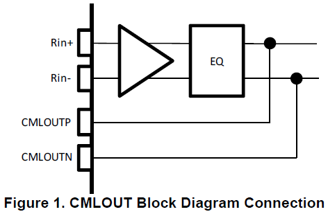
    1. There is a way to access the inputs after the EQ of the DS92LX1622 using Pin 32 (CMLOUTP) and Pin 33 (CMLOUTN):

    To enable the CML output for these pins, perform the following steps:

    • Use the true clock source of the application to trigger the scope. Normally, this is the transmit pixel clock of the transmitter.
    • Enable CML Output by setting Register 0x3F[4] = 0
    • Notes:
      • Do not enable CML Output during normal operation(0x3F[4] = 1)
      • Do not enable SSC during this measurement
    • For general purpose 100 Ohm STP cables, Reg 0x27 = 0xE0 provides the most margin.

    2. There is no contradiction with the datasheet statements. ISI will result in frequency-dependent signal attenuation. Since data is comprised of multiple signal frequencies, the 10m STP cable will not attenuate the low-frequency content as much as high-frequency content. The serial bitstream will not be attenuated uniformly according to the expected ISI. Therefore, the 180 mVpp minimum input signal amplitude requirement can therefore be met, especially since transmitter devices are outputting at least 536 mVpp (see VOD CML Driver DC Specification). 

    Regarding your question about input jitter tolerance of 0.53 UI, this is the jitter tolerance allowed by the internal PLL to retain lock to the input after the signal passes through the EQ.

    3. If you use the procedure shown above to enable the CML output, then you can see the effect of the CML output after the EQ:

    4. Unfortunately, we do not have an IBIS-AMI model or other representative model we can provide for the high-speed channel. I advise using the method shown in the answer to Question 1 to view the output after the EQ.

    5. The best way to observe the PLL bandwidth of the DS92LX1622 is to reference Figure 23 in the datasheet. The jitter tolerance curve roll-off at higher frequencies shows the approximate frequency limit of the PLL bandwidth, beyond which the PLL will attenuate jitter and can lose lock if the jitter at these higher frequencies are beyond the allowed jitter amplitude.

    Thanks,

    Michael

  • Dear Michael

    Thank you for your reply and suggestion.

    I have a question about answer 2., could you please advise.

    According to VOD CML Driver DC Specification, VOD is Output Differential Voltage.
    On the other hand, datasheet P.14 of Figure 11. Serializer VOD DC Diagram is single end Voltage.
    Which is correct?

    By the way, I made a waveform evaluation method, what do you think of it.
    Could you please oversee listed below.
    if OK, I send the customer and use.

    (1)Comfirm DS92LX1621 output eye pattern, it is within the spec of output voltage.

    (2)The cable insertion loss is less than 14dB at maximum frequency range in actual condition
    and it is followed loss curve of frequency square root propotionally

    (3)Observe CML OUT of DS92LX1622, eye- pattern is opened more than 0.52UI.

    I appreciate your great help and cooperation.

    Best regards,
    Shinichi
  • Hi Shinichi-san,

    Figure 11 shows the output measured both single-endedly and differentially. They are both correct.

    The top diagram only shows VOD+ or VOD-, meaning that only one polarity is measured. If you measure only DOUT+ or DOUT-, you can expect a waveform with an offset of VOS, similar to the Single-Ended waveform. The bottom diagram shows the difference when subtracting (VOD+) - (VOD-), taken when you measure (DOUT+) - (DOUT-). When measuring the differential waveform, you can expect to see a waveform centered at 0-V with an amplitude equal to |VOD| specified on p.8, with the peak-to-peak difference being double the amplitude shown on p. 8.

    Your waveform evaluation method looks good to me.

    Also, I would recommend to double-check that the customer has DS92LX1622 Reg. 0x27 = 0xE0. This register is related to back-channel communication echo cancellation, and we have found that with most industry standard cables, a value of 0xE0 yields optimal performance.

    Regards,

    Michael
  • Dear Michael

    Thank you for your reply.

    I understand VOD+, VOD- and |VOD|.

    I'll make him know your advice.

    If he has an additional question, I'll ask again.

    I appreciate your great help and cooperation.

    Best regards,
    Shinichi