


Other Parts Discussed in Thread: DS90UB948-Q1
We Have An Automotive Head Unit Design Consists Of 2 Units : Display Touch Combo Module Device And Main Head Unit ECU As Below
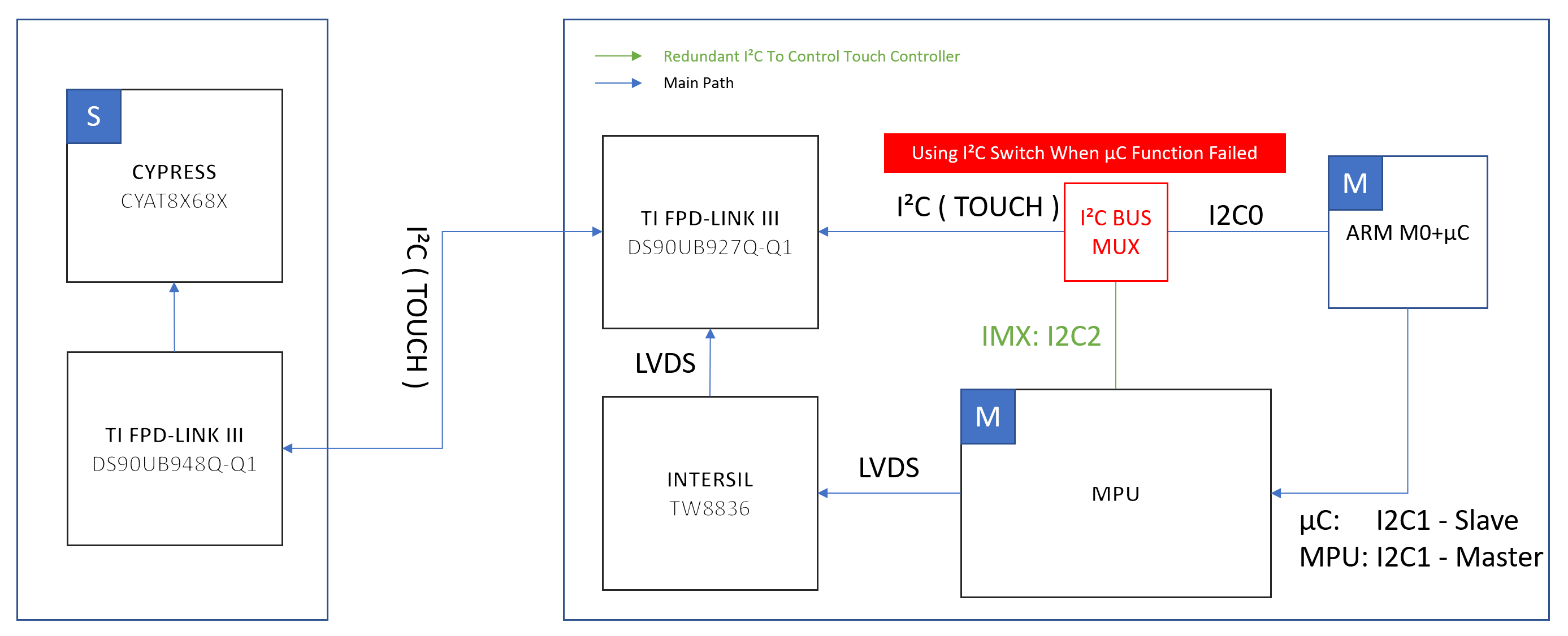
We Need Your Helps To Confirm Our Questions From Our Block Diagram. As You See From Our Block Diagram We Use Both Of Microcontroller ( In Block Diagram µC ) And Application Processor ( In Block Diagram MPU ) To Prevent Touch Control Function From Failure. Our Design Is Due To Functional Safety Requirement So We Use Another Logic I2C Bus Multiplexer As Switch And Keep Either Of MPU And µC For An Redundancy. And As You See From Our Block Diagram The ECU Side Use DS90UB927Q-Q1 Serializer LINK Through A Cable Wire To Connect Display Touch Combo Module Device. In Our Case We Use I2C And BCC To Get I2C Data From Touch Controller. Our Questions Are:
1. For Redundancy Design The MUX Switch Seems Necessary But May Cause A Latency?
2. Does TI Have Suitable I2C Bus Selector / Bus MUX Switch For Design Case Like Ours (The Recommended Parts Shall Be AEC-Q100) ?
3. From Datasheet Of DS90UB927Q-Q1 Pin 9 / 10 / 11 Can Be Used For Remote I2C Through FPD-LINK. But We Don't Really Understand What Is Pin 18 PDB For?
4. To Link DS90UB927Q-Q1 We've Checked The Datasheet Of Deserializer Side DS90UB948-Q1. The Dual FPD-LINK III Deserializer Device Only Has 1 Set I2C Pin 45 / 46 / 47. Our Question Is Does The DS90UB48-Q1 Allow Multiple I2C Master?
