Other Parts Discussed in Thread: DS90UB934-Q1
Hi everyone,
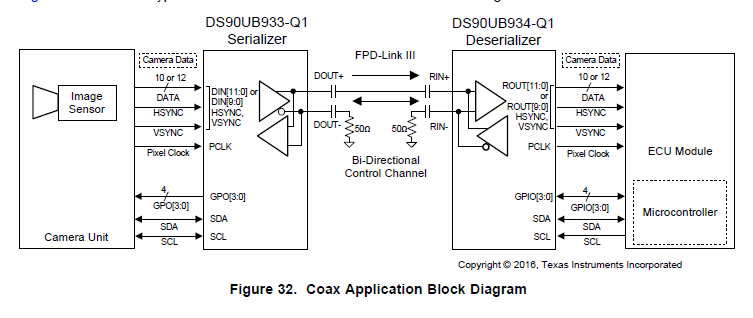
In our application, use ds90ub933 & ds90ub934 to transfer video signal over coax cable, the block diagram as follows
the detailed information about video signal from sensor as follows
format : 12 bit pclk : 74.25M resolution : 1290 x 960
all the control channel(I2C) access from cpu to serializer/deserializer/camera are all normal.
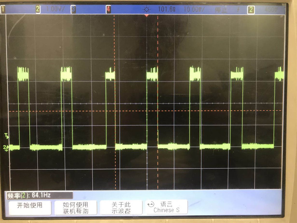
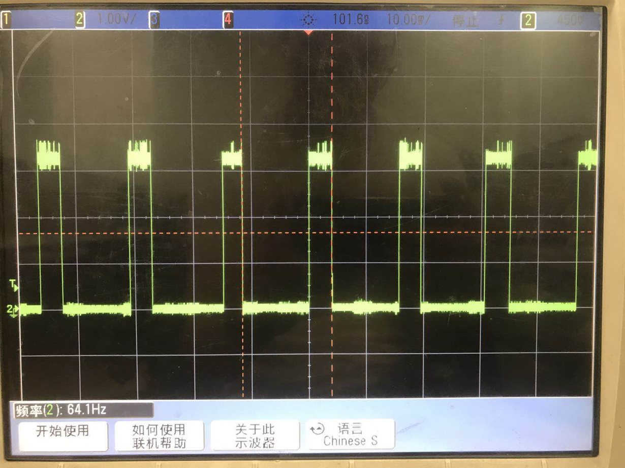
After the sensor start to work, we can test the pclk signal in sensor side is normal, but seems to be abnormal in cpu side, as well as in ds90ub933 side.
when read datasheet about ds90ub933, we have some doubt about the following content.
7.3.2 Line Rate Calculations for the DS90UB933/934
The DS90UB933-Q1 device divides the clock internally by divide-by-2 in the 10-bit mode and by divide-by-1.5 in
the 12-bit mode. Conversely, the DS90UB934-Q1 multiplies the recovered serial clock to generate the proper
pixel clock output frequency. The following are the formulae used to calculate the maximum line rate in the
different modes:
• For the 12-bit mode, Line rate = ƒPCLK × (2/3) × 28; for example, ƒPCLK = 100 MHz, line rate = (100 MHz) ×
(2/3) × 28 = 1.87 Gbps
• For the 10-bit mode, Line rate = ƒPCLK/2 × 28; for example, ƒPCLK = 100 MHz, line rate = (100 MHz/2) × 28 =
1.40 Gbps
My question
if the pclk from sensor is 74.25M, , the pclk output from DS90UB934-Q1 should be still 74.25M, not (74.25M / 1.5), is it right ?
However, in our application, we can monitor the pclk in DS90UB933-Q1 side is 74.25M, but the pclk in DS90UB934-Q1 side is 74.25M / 1.5, not the expected 74.25M,
it seems that the DS90UB934-Q1 does not recover serial clock to generate the proper pixel clock output frequency ?


