This thread has been locked.

If you have a related question, please click the "Ask a related question" button in the top right corner. The newly created question will be automatically linked to this question.

DS90UB953-Q1EVM: Evaluation board for STP or STQ

Part Number: DS90UB953-Q1EVM

Hi team,

I have some questions for DS90UB953EVM and DS90UB954EVM.

#1

Our customer is considering STP or STQ cable, but 953EVM and 954EVM are for Coax.

Are you planning to release an evaluation board for STP or STQ cables?

They want to obtain a STP or STQ evaluation board for reference.

#2

If an error is detected by CRC error check etc. and fail is written to the register, is there any way to recognize this other than reading the register?

For example, the followed registers:

 0x5D --- CSI_ERR_STATUS

 0x5E --- CSI_ERR_DLANE01

 0x5F --- CSI_ERR_DLANE23

 0x60 --- CSI_ERR_CLK_LANE

 0x4D --- RX_PORT_STS1 (only 954)

 0x4E --- RX_PORT_STS2 (only 954)

 0x7A --- CSI_RX_STS (only 954)

#3

They want to know the frequency dependence of EMC characteristics.

Is there any EMC test result of some frequencies?

Best regards,

Tomoaki Yoshida

  • Hi team,

    Any update on this issue?
    It is helpful for me if there is partial answer.

    Best regards,
    Tomoaki Yoshida
  • Hi team,

    Any update on this issue?

    Best regards,
    Tomoaki Yoshida
  • Hello Yoshida-san

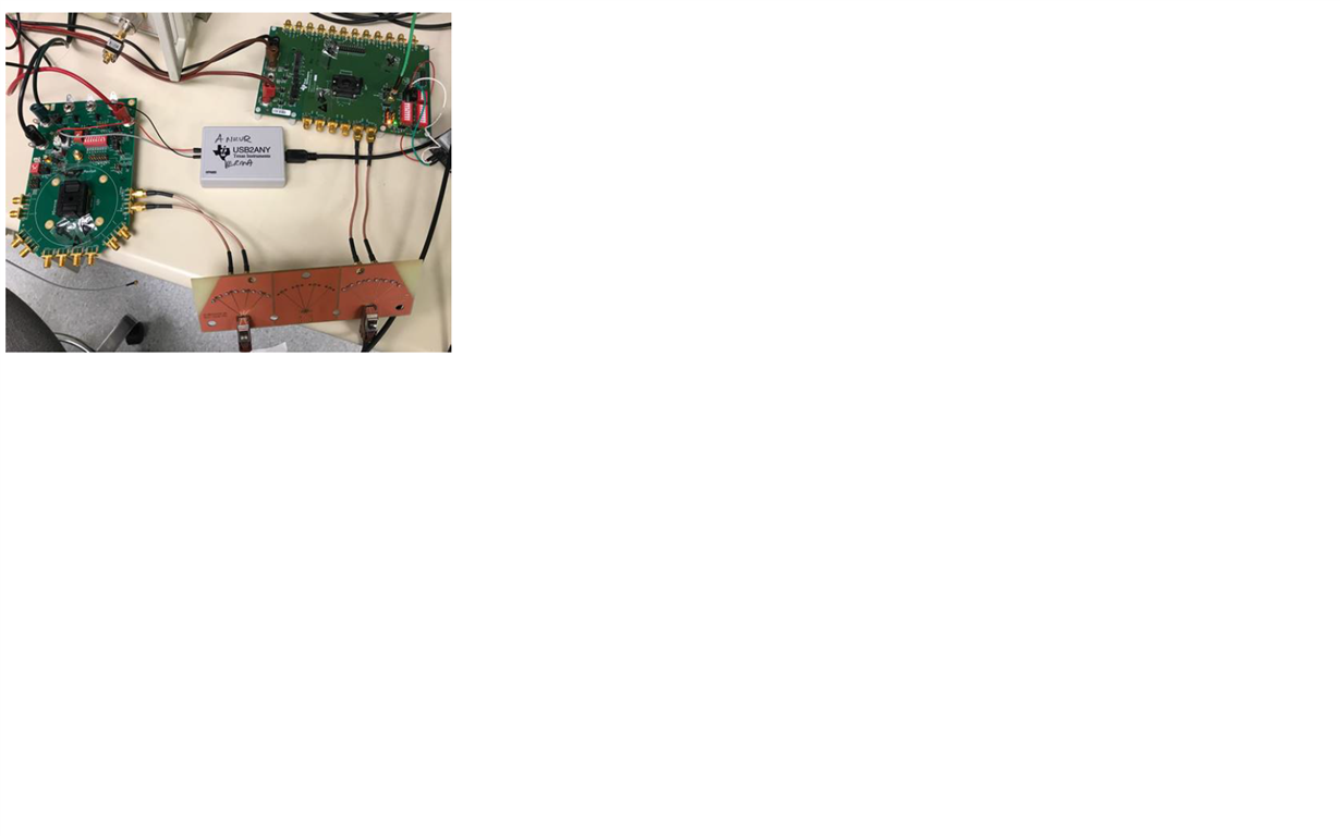
    1. We have SVBs (very limited quantities) with SMA's . These can be connected to an SMA-STP daughter card and then to an STP cable. A picture of this setup is attached.

    2.CRC error indications are available only through the Register access

    3.Can you clarify whether the question is about Immunity or Emissions? If they are emissions then they would be related to the FWD channel data rate as well as csi-clock from the Imager

  • Hi Vijaya-san,

    Thank you for your support.

    1.

    You mean that you will not be preparing an evaluation board for STP in the future?

    We are considering the use in STP and we believe that a mechanism for establishing communication is necessary for reference.

    3.

    I meant the data of Emmission.

    Because we think that it depends on FWD channel data rate, I would like to know how the emission test results will affect when swinging the clock frequency.

    Best regards,

    Tomoaki Yoshida

  • 1. As I had shown in the picture, we have an SVB with SMA's attached and this can be connected to a daughter card with SMA to STP conversion. This can be used as a board for establishing the connection.

    2. Emissions are dependent on all the clock signals as well as on the FWD channel data rates. Emissions can show up at fundamental, as well as sub-harmonics and even/odd harmonics. As long as the cable is shielded and lines are properly terminated and grounded emissions can be kept under check

    Regards
    Vijay
  • Hi Vijay-san,

    I'm sorry for the late reply.
    We may send images of various sizes with FPD-LINK.
    I will eventually evaluate the emission depending on the data rate, but I am happy if there is an EMC test result for each data rate as a reference.

    If there is the these data, please tell me.


    Best regards,
    Tomoaki Yoshida
  • Yoshida-san

    We support infinite resolutions on data rates and resolutions on FPD Link. We do not collect emission data for every resolution. Emissions are primarily a system level specification that usually our customers deal with by proper shielding and proper grounding of the system. We can provide guidelines to the customers but we cannot provide emission at every pclk rate as this is physically impossible.