This thread has been locked.

If you have a related question, please click the "Ask a related question" button in the top right corner. The newly created question will be automatically linked to this question.

DS90UB914A-Q1: Signal Detection and LOCK Detection Circuit

Part Number: DS90UB914A-Q1

[ DS90UB914A-Q1 ] Signal Detection and LOCK Detection Circuit

Hi,

Can you please clarify the circuit or point where signal and lock are detected respectively?
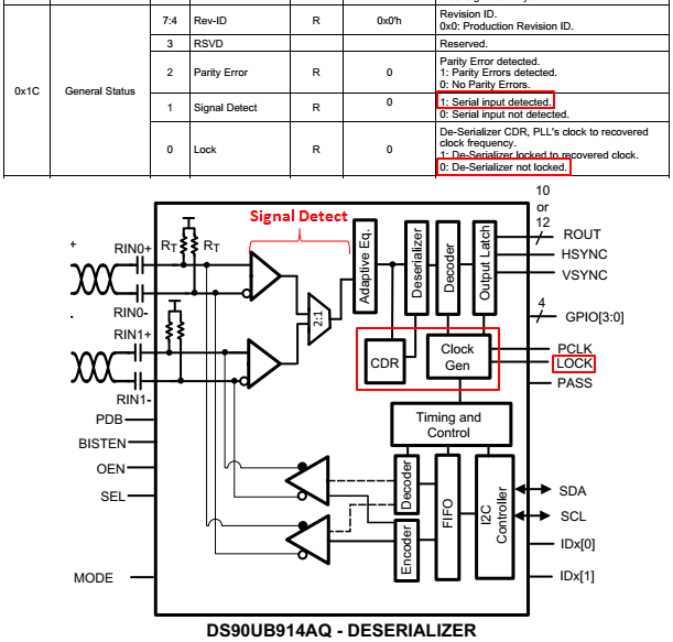


At production line, customer has found that the camera image was corrupted. According to system log which DS90UB914A-Q1 is used, when this error happen, the log indicates 0x1C[0] = 0 (not locked) and 0x1C[1] = 1 (input detected). From this log, it's assumed that the out of lock condition happen, even though valid input signal appeared.

Q1: Whether the valid signal appearred or not is detected at the input stage (before signal going to CDR block).
Correct?

Q2: What situation can be expected that detect 0x1C[0] = 0 (not locked) and 0x1C[1] = 1 simultaneously?


Thanks,
Ken

  • Ken,
    The signal detect bit shows whether any signal is present at the FPD-Link input or not by detecting the frequency input and what rate it is toggling at. It is typically used to detect cable fault condition.
    Is the LOCK stuck at low (static low or low only sometimes)? If the lock is stuck low make sure clock/data/sync is present at ser input and the correct polarity is connected to the deserializer. If the LOCK is only low sometimes it can be caused by power supply noise or quality of input PCLK or the serial data eye.
    They can also look at the datasheet for other diagnostic features such as BIST.
  • Thanks, Palaniappan