This thread has been locked.

If you have a related question, please click the "Ask a related question" button in the top right corner. The newly created question will be automatically linked to this question.

LMH1218: Alignment Jitter in SL12G and LMH1218 not locking to any rate.

Part Number: LMH1218

Hello,

We use the LMH1218 extensively in our product range and have been pleased with the performance of the device. However, we recently designed a product that will output SL12G video and this has highlighted a couple of problems.

Previously we have used the device for 3G video outputs and not had any problems with video performance. On the new board with that provides a SL12G video output, the video and eye pattern are fine but we have quite high alignment jitter. On investigation we found that the LOCKED signal on pin 16 of the device is low suggesting that it is not locked to the incoming 12G and passing the video through RAW as a result without retiming/reclocking. 

We checked the LMH1218 on our previous boards operating with 3G video that have good video performance and discovered that when monitoring pin 16 they are also not locked?

We know that we are writing to registers successfully as we can see the effect of changing parameters through them. When we are using 3G video we are able to adjust register OUT0_VOD (0x80.)

However, as soon as we try to set any value for register 0x80 in 12G, the output is switched off and we do not get an eye pattern?

Below are the registers we set for initialisation and control with the register 0x80 setting commented out.

{0xFF, 0x04, 0x07}, //enable channel control

            {0x16, 0x25, 0xFF},

            {0x3E, 0x00, 0x80},

            {0x55, 0x02, 0x02},

            {0x6A, 0x00, 0xFF},

            {0x03, 0x00, 0xFF},

            {0x0A, 0x0C, 0x0C}, // Reset CDR

            {0x0A, 0x00, 0x0C}, // Release Reset

            {0xFF, 0x04, 0x07}, // enable channel control

            {0x31, 0x01, 0x03},

            {0x2F, 0x00, 0xC0},

            {0xFF, 0x04, 0x07}, // enable channel control for VOD level adjust

            //{0x80, 0x44, 0xFF}, // VOD level adjust

            //{0x0A, 0x0C, 0x0C}, // Reset CDR

            //{0x0A, 0x00, 0x0C}, // Release Reset

            {0x84, 0x03, 0x03}, // Power Down out 1


            {0x0A, 0x0C, 0x0C}, // Reset CDR

            {0x0A, 0x00, 0x0C}, // Release Reset

            {0xFF, 0xFF, 0x00}

Could you please let me know if we are setting these correctly and in the correct format?

Thanks in advance,

John.

  • Hi John,

    I reviewed your register settings.

    1). First of all, at 3G-SDI, device should be able to lock without register initialization. I suggest if we can try first to understand why at 3G there is no lock. So please just power up the device and make sure signal is present. Device should be able to lock under this condition. 

    2). At 12G-SDI, lmh1218 has input equalization to compensate for long trace - about 10 to 20 inches of FR4. If signal source is too close by, lmh1218 may do over-equalization and this may cause lock failure. Therefor this is why we have reg 0x003 = 0x00 in the initialization routine. So for 12G-SDI you may need to initialize the device.

    3). Please note you can use minimum register settings below. With these settings lmh1218 should be able to lock ao any data rate:

    {0xFF, 0x04, 0x07}, //enable channel control

                {0x16, 0x25, 0xFF},

                {0x3E, 0x00, 0x80},

                {0x55, 0x02, 0x02},

                {0x6A, 0x00, 0xFF},

                {0x03, 0x00, 0xFF},

                {0x0A, 0x0C, 0x0C}, // Reset CDR

                {0x0A, 0x00, 0x0C}, // Release Reset

    4). Can you please send us your schematic and pcb layout?

    Regards,,nasser

  • Thank you for the quick reply Nasser,

    Please see my replies below.

    1). First of all, at 3G-SDI, device should be able to lock without register initialization. I suggest if we can try first to understand why at 3G there is no lock. So please just power up the device and make sure signal is present. Device should be able to lock under this condition.

    I agree that we concentrate on getting the 3G locking. We are still having problems with the 12G but  we have now got the LMH1218 locking in 3G.

    We had tried the test you suggested previously and yes, with no register initialization at all the device would lock in 3G but it would not lock with the minimum register settings for initialization.

    We had to change the way we were Reading/Writing to/from registers. Previously we were just writing a register data byte and a mask byte. What we do now is to read the register, mask the bits we don't want to change e.g. Reserved Bits, write back the modified data byte and mask.

    For example, we are setting a value in register 0x80.

    0x80 0x40 0xF0.

    What we do now is to read register 0x80, mask the bits we don't want to change e.g. Reserved Bits, write back the modified data byte (0x40) and mask 0xF0. The device is locked and the eye pattern amplitude changes accordingly.

    However, we can change the value to e.g. 0x44 and we get a different eye pattern amplitude even though it is masked with 0xF0 which should not allow the bottom 4 bits to change?

    Is it necessary to write the mask to the device?

    Thanks in advance,

    John

  • Hi John,

    LMH1218 or other SDI devices uses Read/Modify/Write. To explain this further, please note the followings example for Read/Modify/Write steps"

    Read:

    a). Read lmh1218 register that you are planning to change. For example you read register 0x80 and the value is 0xA5 (note this is just an example to make Read/Modify/Write operation more clear).

    Modify:

    a). Your micro-controller, FPGA, or ASIC - in it's local memory - preserve bits that you do not want to change. For example, here we want to preserve lower nibble (reserve bits which is equal to 0x5).

    b). Micro-controller/FPGA/ASIC in it's local memory changes the upper nibble (0xA) ONLY - bits that you want to change - and let's say you change this value to 0xB.

    c). Micro-controller/FPGA/ASIC in it's local memory does  logical binary operation to create new 8 bits together (for example you logical OR 0xB0 with 0x05) and the result is 0xB5. 

    Write:

    a). Finally, Micro-controller/FPGA/ASIC does a write operation and writes back 0xB5 back into lmh1218 register.

    Given these steps, we preserved bits that we did not want to change(i.e lower nibble) and just changed higher nibble that we wanted to change and wrote back the final value

    As you can see, in your example you should write back 0x40 because reserved lower nibble has 0x0 value. Hope this make it clear.

    Regards,,nasser 

  • Thank you for the excellent support Nasser,

    There was a problem where we were not carrying out the Read, Modify, Write process correctly. We now have the devices locking in 3G and 12G with good eye patterns.

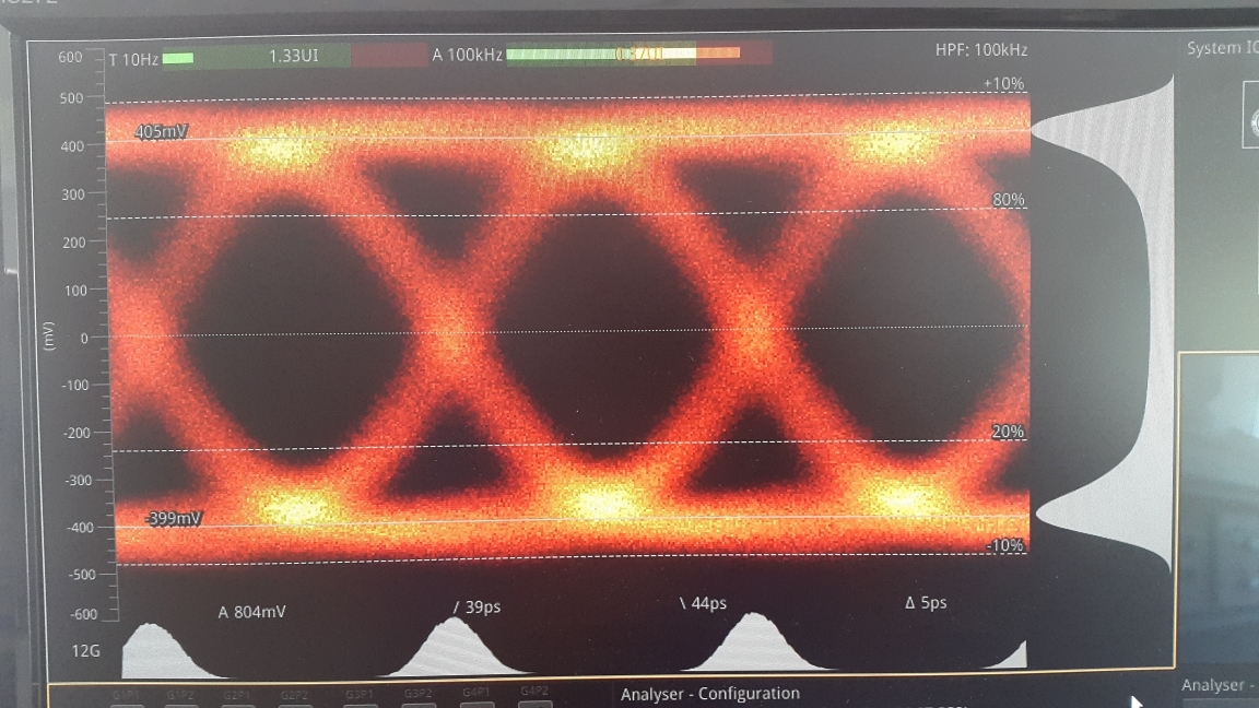
    However, in 12G we are still having a problem with Alignment Jitter (please see below.) Our trace length from the output of the LMH1218 to the coax connector is only approx 10mm and so we set the CTLE register 0x03 to 0x00 for minimum boost setting on initialization. We also tried setting 0x13 to 0x02 to bypass stage 3 & 4 of the CTLE but this didn't seem to have any effect.

    We have checked the layout considerations and have clearance around the devices and traces. Do you have any other suggestions that we could try to reduce the Alignment Jitter in 12G?

    Thank you in advance,

    John.

  • Hi John,

    LMH1218 or other 12G SDI devices loop bandwidth is typically around 13MHz. This means any jitter less than 13MHz is going to pass through the lmh1218 device. On the other hand, jitter higher than 13MHz would be attenuated.

    I am thinking perhaps your video source may have jitter within the loop bandwidth(less than 13MHz). Or there could be a setup issue.

    when measuring alignment jitter please make sure you use short - 1m - good quality cable. Additionally we should use color bar pattern as well. Please confirm.

    Regards,,nasser
  • Hi John,

    Can we go ahead and close this thread ? Please let us know the latest status on this.

    Regards,,nasser
  • Hello Nasser,

    Thanks again for your support. I think we are nearly there.

    We are using 1M Belden 4694 with 12G BNCs and colour bars for alignment jitter tests.

    We tried adjusting the output PLL bandwidth on the source device but found it made matters far worse. The default for this device is 0.13 Mhz and that yields the best results.

    The Phabrix QX allows the alignment jitter monitor to be triggered on a single line and with the filter set to 10Khz we can see that is not flat. The alignment jitter figure is representing the peak to peak measurement of this and so it is high.

    We found that this is not a fixed frequency causing this effect. It changes with video content. With live video we see additional undulations appearing in this display representing the alignment jitter?

    At 59.94P the effect is less and the Alignment jitter is actually then within specification.  Please see below...

    59.94P

    50P

    I think this could perhaps be to do with our source video rather than the LMH1218 but please let me know your thoughts so that we can be sure to eliminate it.

    Thank you,

    John

  • Hi John,

    Alignment jitter is a band pass filter measuring jitter from 100KHz up to the one tenth of the data rate. Based on how clean or how jittery is the source video transmit clock/content and if the jitter is within the loop bandwidth of the LMH1218, this has wide impact on the overall alignment jitter measurement result. There are video sources with 0.12UI, 0.22UI or even 0.28UI of AJ. In summary, this is related to the video source FPGA/ASIC implementations. SMPTE specifies color bar with 1m  cable however there is no golden unit and FPGA/ASIC implementations are different from one vendor to another and this has wide impact on this measurement.

    Regards,nasser

  • Hi John,

    Could you please provide us status on this issue? We would like to close this thread.

    Regards,,nasser
  • Hi Nasser,

    Thank you for your excellent support. We are confident that we are now configuring the LMH1218 correctly. The alignment jitter is good at 50P now but still slightly high at 59.9P but we are pretty sure that this is not related to the LMH1218.

    Please go ahead and close the thread.

    Thanks,

    John
  • Hi John,

    Thanks for the update. We'll go ahead and close this item.

    Regards,,nasser