This thread has been locked.

If you have a related question, please click the "Ask a related question" button in the top right corner. The newly created question will be automatically linked to this question.

TCA9509 NOT Repeating the ACK

Other Parts Discussed in Thread: TCA9509, TCA9517

TCA9509 is used by customer with Side A as slave (batter pack, 3.3V SMBus) to Side B (MCU 5V SMBus)

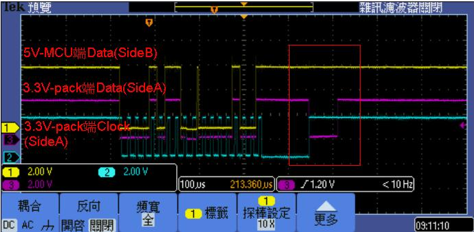
it is observed that there is ACK on side A but it is not repeated at side B

MCU data pin is set as input mode

circled in red below, Side A data purple CH has pull low

Side B data yellow CH however, didn't...what might be the cause?

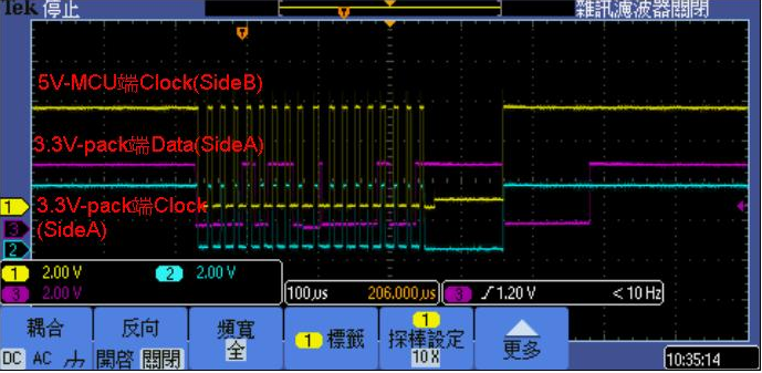
the clock from side A and Side B seems normal

  • Hello John,

    The images you inserted are not seen.  Here is a link to a post that shows how to insert images.

    https://e2e.ti.com/group/helpcentral/f/301/p/326068/1139292#1139292

    -Francis Houde

  • Thanks very much for the reply, i have re-uploaded the images.
    please help check if they are visible.
    Thanks
  • any comments are appreciated

    Thanks

  • Hello John,

    Can you provide a zoomed in view on the missing ACK pulse? In particular, I am curious about what the VOL/voltage is on the purple trace when it is not propagated to the yellow side.

    Please note that the TCA9509 has a low VIL on the A side of 0.3 V.

    This can be seen in the recommended operating conditions in the data sheet.

    Also, you mentioned that your master was in input mode?
    Can you confirm this? When I count the clock pulses in the waveform, you look like you're missing a pulse for the ACK. The first ack looks good, but the second one should occur where the long clock stretching event looks like it is happening. The weird thing is that the slave does not seem to pull down on the bus until the rising clock edge? This doesn't seem to comply with i2c communication specification.
  • Hi Jonathan,

    In TCA9509 DS (page 8) it mentions that

    "any arbitration or clock stretching events require that the low level on the A-bus side at the input of the TCA9509 (VIL) be at or below 0.15 V to be recognized by the TCA9509 and then transmitted to the B-bus side."

    I am not sure what it means. We have a 0.3 VIL but there is also a VILC with typical 0.15V (guess this is for the stretching mentioned above?) My understanding is on a stretching event, the input low should be lower than 0.15V but how does TCA9509 detects a stretching event? I am confused here with 0.3V VIL and 0.15V VILC.
  • Hello, Jonathan,

    Thanks very much for the reply, sorry, somehow i didn't get the notification and wasnt aware of your post earlier.

    The customer had intentionally remove a stop command at the end, and i think that's you seeing it not comply with i2C spec.

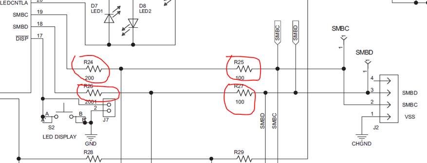
    Kenny, has performed some testing and if we remove the circled resistor. the communication using TCA9509 works ok.

    which means the voltage wasn't low enough for the repeater. However, the battery pack design can not be changed (TI gauge reference design)

    can you please help clarify Kenny's question?

    how does the TCA9509 detects the clk strech and decides to lower voltage threshold to determine the line low.

    Thanks very much for the support

  • Kenny and John,

    The VIL of the TCA9509 is 0.3 V, and the VILC (the 'C' means contention, which means that 1 or both sides are driving low).

    Basically what it says is that if any side is driving low, the A side will not recognize a valid low until 0.15 V. This really means that if something on the B side is driving low, and the A side is outputting a low, then the external device must pull the voltage below 0.15V in order to hold the B side low (if/when it releases in a clock stretching event). 

    These differences in voltage are how the device prevents itself from getting stuck transmitting 0.

    If I were to try and verbally explain this process of detecting a clock stretch event, it is the following:

    B side pulls low, which causes the A side to pull low.

    Device on A side also pulls low (the TCA9509 A side and the device on A side are now both pulling low on the bus, both pull-down fets would be in parallel and drop the voltage on the bus more, down to 0.15V or less). Since their combined pull-down on the A side makes voltage fall under 0.15V, the TCA9509 recognizes that a device on the A side is also pulling low, and it will rely on that signal for determining when to release the B side pull-down.

    Device on B side releases the bus, but because the TCA9509 B side pull-down is active (because device on A side is helping pull bus below 0.15V threshold), the B side stays low. 

    This is a clock stretching event.

    The series resistors make sense that they would cause the problem. Depending on which side you want to put the master on and what your voltages are, another possible translator/buffer option could be the TCA9517. It has a VILC of about 0.45 V which should be more tolerant of higher voltages.

  • Hi Jonathan,

    Thank you for the explanation.

    I was suspecting that the problem may be due to the VILC. But since the yellow line (Side B, master device) is not driven low, now it looks the problem is because the low on purple line (side A, slave device) might not be low enough (< 0.3V) due to the two series resistors on the bus. ( I will have to ask the customer to measure exact how low the voltage is on the purple line). TCA9517 might also be a solution, it also have a higher VIL (VCCA * 0.3V) according to the DS.

  • hi Jonathan

    Thanks very much for the recommendations, Customer has tried with the TCA9517 and the previous issue will no longer happen