This thread has been locked.

If you have a related question, please click the "Ask a related question" button in the top right corner. The newly created question will be automatically linked to this question.

TPL0102-100 Looses its setting on power-cycling

Other Parts Discussed in Thread: TPL0102-100, LMV358

Hi All,


I am using the TPL0102-100 in two identical circuits as potentiometers to provide a command voltage to two identical current sinks.  There are two of these circuits on each PCB (two TPL0102 ICs controlling four current sinks).

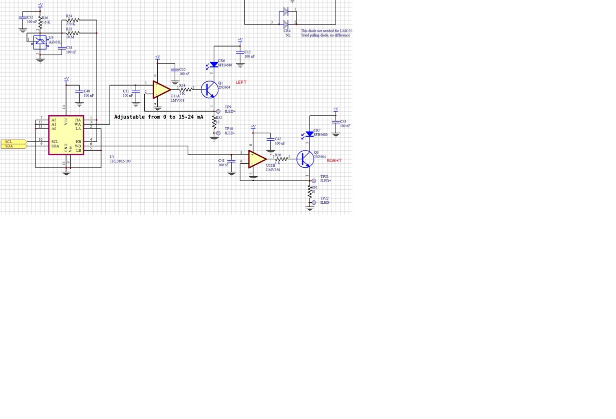
Briefly: the system runs on 4.5-5V.  The HA & HB pins are driven from the output of a voltage reference at 1.25V.  The LA & LB pins are ground and the wipers are connected to the non-inverting inputs of LMV358s.  The LMV358's are configured as current sinks driving the base of 2N3904 BJTs through a 1K resistor.  The emitters of the 3904's are connected to ground through 10 ohm resistors and to the inverting side of the LMV358s.  There are 100 nF capacitors on each wiper.  The supplies, op-amps and TPL0102s are properly bypassed with 10 uF and several 100 nF ceramics.


I am able to program the pot resistance and the load current follows the pot settings.  The test program allows me to adjust the volatile pot settings, then on command, copy the values into EEPROM for non-volatile storage.  I am displaying both the volatile and non-volatile registers and see both sets of registers are properly set.  After I set them (permanently), I disconnect power for several seconds and reapply power.  Both the A&B pots on both chips have returned to their default values 0x80.  One chip is strapped for address 0 the other for address 1.  I am controlling the pots with their I2C interface.  Both pins 1 & 8 are grounded.  The entire system (pot, opamp, I2C controller runs on the same power-supply, although there is a 10 ohm sampling resistor between the I2C controller supply and the TPLs.  The is less than a 1/2V difference between the supply levels and usually less than 200 mV.  Do you think the supply differential could be causing the issue?

All comments welcome.

Thanks for your help.

Scott

  • Hello Scott,

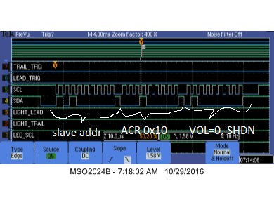
    Can you let me know what your command sequence is?  What are you writing to the ACR (0x10h)?  Is VOL 0 or 1? 

    If you have a schematic or diagram that would also be helpful.  I am not sure I understand how your are connecting supplies for I2C controller and TPL's?

    -Francis Houde

  • Hi Francis,


    I've attached a couple of schematic fragments and a script before and after power is cycled showing the default values instead of those programmed into the pots.  ckt shows the TPL pots and the current loads they control, ckt1 shows the system, a tester PCB, that supplies power to ckt via pins 1 & 2 of connector P2.  So you see I power the device from the USB supply, and place a 1 ohm (R16) along with U5 to sample the PCB current.  Typically the PCB draws 50 mA or so.  Originally, R16 was 10 ohms and I was concerned that the supply voltage on the TPL (U4) was 1/2V lower than the I2C signals and this was causing the resetting issue.  I had a chance to check that out this evening by lowering R16 to 1 ohm thus reducing the drop to around 50 mV below the I2C high levels.  This made no difference to the TPL0102 losing its settings.


    I have an interactive mode that allows a user to adjust the LED current based on illumination measured elsewhere.  The user selects one of the four LEDs and adjusts it while monitoring its emitted light level and the total board current.  During this time, the VOL bit is high to access the volatile pot settings.  Once all LEDs are adjusted, another command copies the settings into the TPL's EEPROM.  The VOL bit is set low during this operation.  I have another command that first sets VOL high and reads and prints all 17 registers, then it sets VOL low and reads all 17 registers again.  This is repeated for both TPL0102 pots on the PCB.  After LEDs are adjusted, and the setting are saved in EEPROM, both sets of registers are equal to the values the user selected during adjustment.  I can repeat the display indefinitely and see the same values.  After a cycle power (unplug USB, wait several seconds then replug), I see the displayed values have all returned to 0x80 for both wipers (address 0 and 1) of both pots.  The -SHDN bit is always high, I never put the pots into low current mode.  When programming EEPROM in the pots, I monitor WIP in the ACR register to prevent writing values before EEPROM programming is complete.

    Thanks for your help,

    Scott

  • Hello Scott,
    Sorry for the Delay. Do you have the specific I2C read and write sequence? Are you toggling the VOL bit before writing to EEPROM? Also, are you checking the WIP bit to make sure that you don't send commands before the non-volatile write is complete?
    -Francis Houde

  • Hi Francis,

    Yes, when saving values in non-volatile registers I monitor WIP.  I am writing to non-volatile settings during testing to arrive at the correct settings, then I write the test values to EEPROM for permanent storage.  I set VOL high to write to volatile registers and low to save the values.  Please look at my last post for a more detailed explanation.

    Thanks for your help,

    Scott

  • Hi Francis,


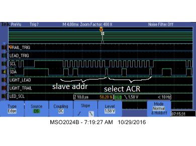
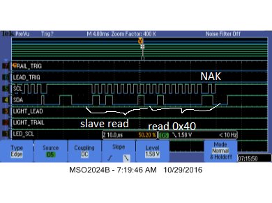
    I hooked up the logic analyzer to verify the I2C bus transactions.  All the transactions look OK, except the pot is not reporting busy when I write to a non-volatile register then read the ACR immediately afterward.  That's the only strange thing I see.


    Also, I wanted to check an apparent paradox in the datasheet.  I'm assuming my interpretation of the VOL bit in the ACR is incorrect.  According to the data sheet, when VOL is low, the non-volatile register set is being accessed.  If that's the case, how does one access the ACR again?  By definition the ACR is a volatile register, so clearing the VOL bit makes is inaccessible if the data sheet is taken literally.

    Thanks,

    Scott

  • Scott,

    Francis is out of the office this week.

    To answer your question about the VOL bit, it does not explicitly turn off all volatile registers. So when it is low, the ACR register will always go to the volatile register.

    If the VOL bit is low, all writes to 0x00 and 0x01 registers should write to both the volatile and nonvolatile registers. The ACR register is always accessible regardless of the state of the VOL bit, page 26 of the datasheet outlines this.
  • Hi Jonathan,


    Thanks for the clarification.

    Any thoughts on why the WIP wouldn't go into the busy state after writing to address 0 or 1 with VOL=0?  I am polling the part about every 50 us during the write operation and don't ever see even one sample showing WIP high.


    My sequence is to enter an interactive mode during which time VOL=1 and I read and write registers 0 and 1 of two different pots (with A0=0 for the 1st and A1=1 for the second), to let the user adjust their values to get some external current sources adjusted (which these pots control).  After the correct pot settings are established, the user enters a command that causes the program to write all the final values into non-volatile registers (0 & 1) of both pots.  During these non-volatile writes, neither of the two pots indicates it is busy even for one sample (firmware will wait for up to 35 milliseconds as long as a pot indicates busy).  I've even changed the code to poll for 10 ms without seeing WIP=1 thinking that the pot was not responding quickly enough with the WIP bit.  This didn't make any difference, the pots don't set WIP in the 10 ms after a write to address 0 or 1 with VOL=0.

    Thanks for your help,

    Scott

  • Scott,

    What I2C bus speed are you running at? If you're not running very fast, the sheer amount of time it takes to read the WIP register would take 3 bytes of data/addresses to be sent before it will even sample the WIP bit. Including start, restart and acks, we are having to send: 29 bits of data. If you're running at 100 kHz, this will take 290 us to send before the device will even read. A write to non volatile memory can occur faster than that.


    In regards to your read and write methods, you may not ever see the WIP bit set high if your I2C bus is slow. That is fine.

    My question is when you change the VOL bit back to 0, do you then perform another write to register 0x00 and 0x01?

    Are you still not seeing the non-volatile memory non-functioning? Or are you considered about the WIP bit not getting set?
  • Hi Jonathan,


    I am running just under 400 KHz, 374 if I remember correctly.


    I would be OK with never seeing WIP active, if data was being retained on power-up, but it isn’t.  When I cycle power the pot returns both wipers to 0x80, midscale, so I suspect something is going wrong with the write.


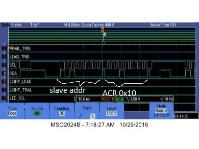
    I set ACR to 0x40 (VOL=0, NSHDN=1), then write to address 0 and 1 (I’ve also tried other addresses which also lose their data on power cycling).


    Thanks,

    Scott

  • Scott,

    Can you send the output from a logic analyzer showing the stream of bytes sent to the device?

    I've tested this functionality on my own bench and it works as expected for me.

    Have you tried swapping parts as well? Does it happen with all parts?
  • Hi Jonathan,

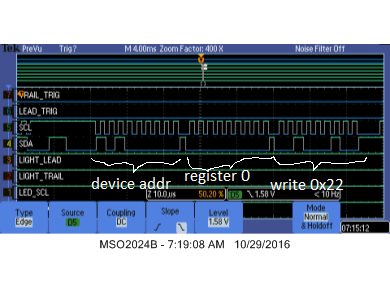
    I've attached 6 images showing the steps I used to write 0x22 to address 0 with VOL=0.

    I have two parts, presumably from a different batch, arriving tomorrow. I'll swap them out. I have two boards each of which contain two TPL0102-100 parts. Both give the same result.
  • Hello Scott,

    Can you try attaching them again, if they're images, you should use the image button in the "use rich formatting" option. I don't see any images.
  • Hello Scott,

    Some of the support staff has been out of the office and we are back logged.  I will try and confirm what you are seeing in the next two days.  Sorry for the inconvenience and I will try to address your issue as soon as possible.

    -Francis Houde

  • Hi Francis,

    Any progress on this issue?

    Thanks,

    Scott

  • Hello Scott,

    I just verified that if write to ACR-Access Crontrol Register address ( 0x10h) with C0 (VOL=1, SHDN=1, WIP=0, bit4-0=0) then write to either IVRA (0x00h) or IVRB (0x01h) with desired  wiper location that once I power down it gets stored into the non-volatile memory.  I think you are writing the wrong hex value to ACR register.  Please try this out and let me know if this fixes your problem.

    -Francis Houde 

  • Hi Francis,

    Your last post contradicts the data sheet.  You said you wrote VOL=1 and the pot recalls your written value on the next cycling of power.  But the data sheet says VOL must be LOW to permanently save a value written to address 0 or 1.  Which is it?


    Also, from the displays I posted earlier, you can see I wrote 0x22 to register 0 with VOL set to zero (as confirmed with a read-after-write check).  When I cycle power and read back the register I read 0x80, the pot's default value.  Furthermore, the pot's resistances are approximately equal between the wiper and the H and L terminals confirming it is indeed set to 0x80.

    Scott