This thread has been locked.

If you have a related question, please click the "Ask a related question" button in the top right corner. The newly created question will be automatically linked to this question.

PCA9306: PCA9306 schematic and layout review request

Part Number: PCA9306

  • Hello Peter,

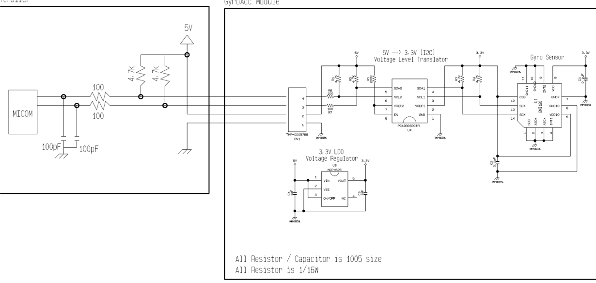
    I have a couple concerns about the schematic. 

    1. Can you tell me what speed they are going to be operating at?  400kHz?  Do you have any information about the capacitive loading of the I2C bus?  Is there a harness or it is a board to board connection?

    2. Are they aware that when the device is connected on the bus they will have both pull ups in parallel? Do they know their total bus capacitive load and what is required for the pull up resistance for their desired frequency of operation?

    3. Also, why are they intentionally putting 100pF next to “MICOM” device? That is 25% of the max capacitive load per the I2C specification (400pF max).

    4. Have they gone through the calculations for Vol given the pull up resistances, series resistors, trace/wire resistance, PCA9306 pass fet resistance, and pull down strength of devices?

    5. Is the board a two layer board? Looks like it, but it should be ok.

    The schematic looks connected correctly. I don’t see any major concerns in the layout.  

  • thanks,

    i will update the 1~3 questions from my customer.

    question 5 : yes the layout is two layer.

    what do you mean Vol ?

    could you share the calculation process about pull up resistances, series resistors, trace/wire resistance ?

  • Hello Peter,

    Please review the following app note.  It will cover the correct selection criteria for your pull up resistors.  I will put together a diagram explaining why Vol is affected by the adding of series resistance. 

    http://www.ti.com/lit/an/slva689/slva689.pdf

    -Francis Houde