This thread has been locked.

If you have a related question, please click the "Ask a related question" button in the top right corner. The newly created question will be automatically linked to this question.

I2C Bus Length

Other Parts Discussed in Thread: TCA9802

Dear Sir/Madam

We have designed one system where we are using 7bit I2C address and connecting 30 slave boards to the Master board on same I2C Bus. My master and Slave boards are connected with PCB or Rigid+Flex PCB.

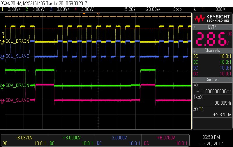
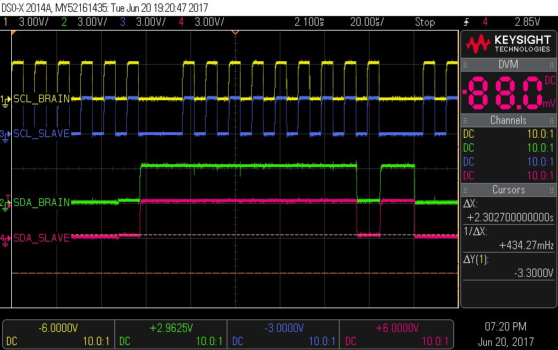
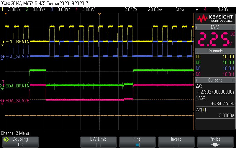
Attached is the I2C waveform which we captured after we connect 10, 20 & 30 Slave to the BRAIN/Master. Brain/master and each slave using 4.7k pull up resistor with 3.3V & each slave is generating its own 3.3V and GND is common in the whole system.

Now my question if we use 10bit address to connect more slave to the same I2C bus, will it be allow me to connect on the same bus without any problem, based on the attached waveform? Can you please guide how we can check and verify the same? The newer slave will be same as earlier 10/20/30 slaves and will have the pull up of 4.7k

In nut shell if we use 10bit I2C address and BRAIN is connected with 1020slaves(BRAIN and Slaves connected with PCB and connector, no cables used to connect them) what parameter we check and how so can be sure that i can physically do the same. Please help/guide so we can expand the system.

Thanks

Krunal Shah

  • Hi Krunal,

    I don't see any issues with the waveforms you provided. In general, as you add more slaves/connections there are a couple of things to be careful of (besides maintaining unique addresses):

    - Additional capacitance, which slows down the signal transitions (particularly the undriven low-to-high signal transition)
    - Lower effective pull-up resistance due to multiple pull-up resistors in parallel, which makes it more difficult for the open-drain driver of each device to generate adequate "low" level voltages.

    The second item can sometimes be addressed by adjusting the pull-up resistances, but in order to maintain data rates the effective resistance needs to decrease as bus capacitance increases. Once a certain point is reached, the best solution is generally to add a buffer device that can help to separate the bus into different segments (each with lower capacitance) and re-drive the I2C signals across them.

    For your reference, here is an application note on selecting pull-up resistor values for I2C buses:

    www.ti.com/.../slva689.pdf

    Max
  • Krunal,

    Just to verify I understand, you currently have 10, 20, and 30 slave devices with 7-bit addressing, and you want to add 10, 20, and 30 more slave devices with 10-bit addressing, is this correct?

    The only limiting factors to how many slaves that can be on one bus is the amount of unique addresses (7-bit = 127, 8-bit  = 256, 10-bit = 1024) and the total bus capacitance can be at maximum 400pF. this is also why, in general, I2C is a relatively short communication distance. So, it is dependent on the devices you are adding as slaves and how much capacitance they add to the bus, along with the inherent trace capacitance. The fastest way to determine this is to add up the known capacitance of each slave device, but you could also observe a known waveform on the bus with the slave devices attached, and determine the capacitance based on the rise time (rise time from 20% to 80% is 1.4Τ, and Τ=RC).

    If I've misunderstood your question, or if you have any other questions, please feel free to post them here.

    Regards,

    Eric Hackett

  • Dear Eric

    Yes you are correct. we want to even more slave then 30. Actually we want to add around 120 to 300 slaves to the master.

    Now our bus capacitance on each board is 22pF (Value which we got from PCB Design tool) so if we connect 30 slaves to the master that will be 660pF capacitance, so we have already exceed the 400pF capacitance range, still we are able to do the communication and from waveform which i share you can see the waveforms are identical of Master and after 30th slave.

    Kindly note on each slave we have uC and that uC is receiving data from Master and use that data to display charters/numbers on LEDs

    So we need to measure the rise time of the Bus (from 20 to 80 %) at the 30th Slave and then do the calculation as below to get exact capacitance, is it correct?

    1.4*4.7k*c = rise time which we get from waveform

    What will be effect of 4.7k pullup on each slave on bus capacitance? Every pull has 3.3V which is generated locally on all slaves.

    Please let us know if any other testing we can do.

    Thanks
    Krunal Shah
  • Dear

    Can you please suggest I2C buffer which we can use on the I2C bus and can expan the system to 1024 Slave. May be we need to add I2C buffer after every 30 or 60 displays that will help us to overcome the I2C limitation.

    Thanks

    Krunal Shah

  • Hello Krunal,

    1) What mode of I2C are you going to use?  Standard? Fast Mode? Fast Mode Plus?

    2)  What voltages (Vcc) are you going to be used on the Master and the slaves?  Do you need translations/level shifting?

    3)  What are the VIL and VOL limits for all master and slave devices.  You need to make sure you don't have mismatches with buffer, master and slaves.

    4)  Are you doing a polling architecture? or is it a broadcast and each slave device has a unique address?  You can use a I2C mux to isolate cap load in a polling architecture or you can use parallel and/or series buffers to isolate capacitive loading.

    5) Estimate how much capacitive load is on the bus, which includes pcb traces, devices, wires, etc.

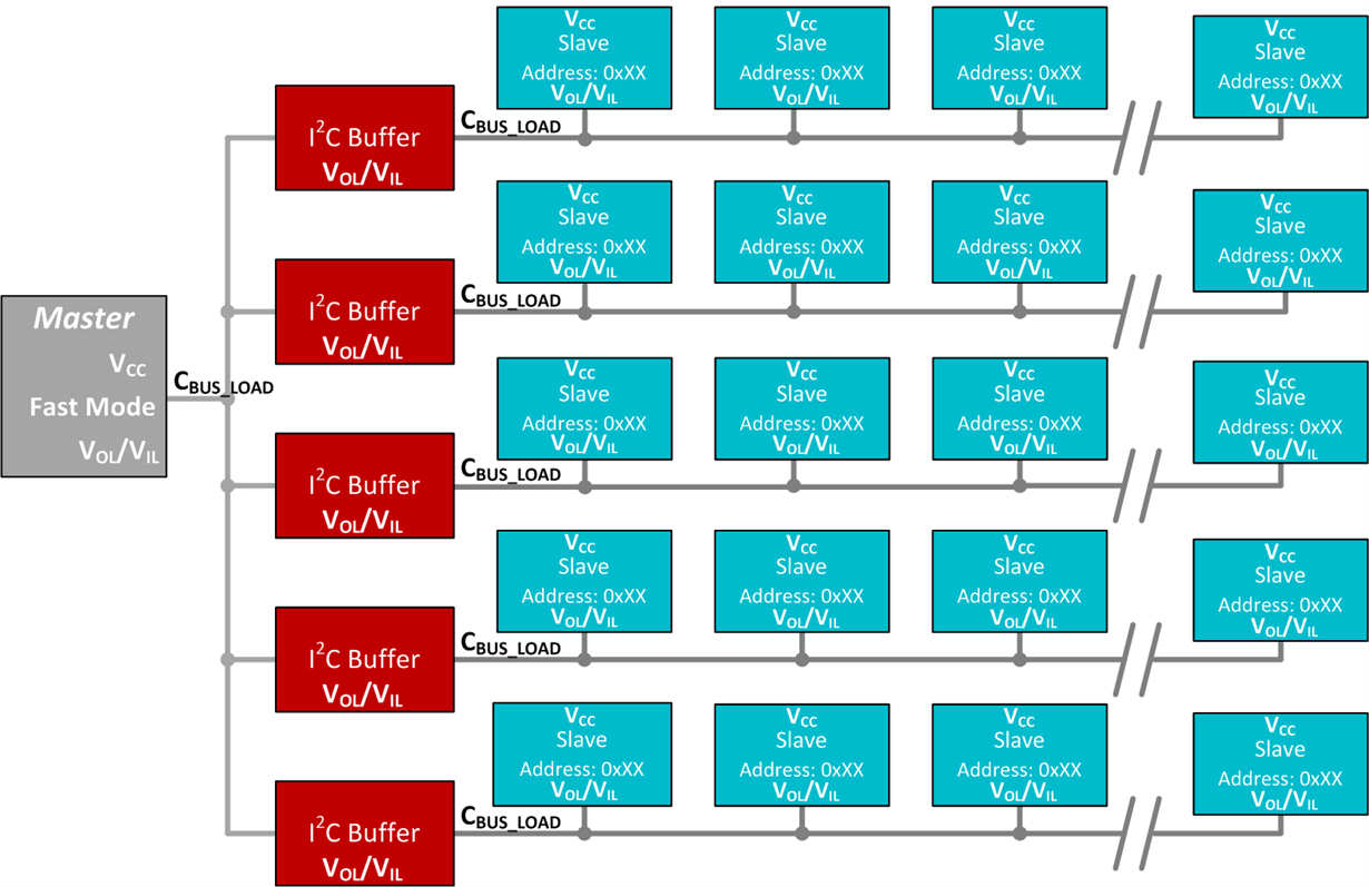
    I have an example diagram that should be useful in filling out.  This will give us a system level idea of what your needs are and then we can recommend the correct buffer or mux.

    -Francis Houde

  • Dear Francis

    Please find the answers below

    1) We are using I2C Fast Mode

    2) We are using same I2C level, both master and slave's I2C working on 3.3V. We just need buffer no translations/level shifting

    3) Master VIH(Min = 2.31V, Max=3.3V), VIL (Min = 0V, Max = 0.99V), VOH(Min = 3.15V), VOL(MAX = 0.15V)

    SLAVE VIH(Min = 2.145V, Max=3.3V), VIL(Min = 0V, Max= 1.16V), VOH(Min=2.4V), VOL (MAX= 0.4V)

    4) we are using  broadcast & using cluster mechanism for Slave ID (10slaves will have same 7bit  slave Id) , We need Series buffers (Our system block as attached for your reference)

    5) Each slave's SDA Line has capacitance of 22pF and Master has 15pF. We are using small bridge PCBs to connect master with slave and slave with slave so no wire connection is there in the system.

  • Hello Krunal,

    I am a bit confused about how you are going to be able to communicate with all the devices if they are on the same bus and have the same address.  Most slaves hard hardware based address, and don't do dynamic addressing.  

    I also wanted to know if you were aware that each slave device can add 5-10pF before you even include PCB trace capacitance.  That should be added to you estimates.  

    Generally speaking most people use MUXs to communicate with multiple devices that have the same slave address.  This achieves two things, it allows you to poll through each slave without having conflicts and it also isolates capacitance so that buffers sometimes aren't needed.    I also see people add buffers in conjunction with MUXs.  

    I think the TCA9802 would be a good option for the buffer.  The TCA9802 doesn't have a static voltage offset and the B side doesn't require a pull up resistor which saves on cost and space.  It also has a constant current architecture that is good for signal integrity.  

    I gather from the previous posts that you want these "boards" to mate in series.  Each of these boards would have 10 slaves, correct?  I am a bit concerned that if you try to stager all these boards in series that you will have some problems in your communications due to accumulation of delays through each board, buffer, and mux.  You may want to look at more of a parallel architecture, especially if you are hoping to attain up to 100's of slave.

    -Francis Houde

  • Dear Francis Houde

    1) Let take an example that we have total 300 slaves connected in the system each slave has 4bit unique id IC mounted on it, but we will use these unique id for the DATA purpose only , not I2C bus unique ID as explained below

    Now we are making cluster of 10slaves each so there will be 30 clusters in the system. Now these 30cluster will have unique ID so there will be 30 unique ID in the system. Now when we broadcast the data to one cluster (Means that data will pass to 10dispays), and in these data we are passing 4bit unique id of the slaves so slave will read the unique ID first and if it is matching it will use that data else it will drop the data.

    So we will be adding these buffer IC may be after 30/60 slaves where our signals of I2C lines are not as desired.

    2) Each slave's SDA Line has capacitance of 30pF and Master has 20pF after adding 5-10pf as you explained.

    3) In TCA9802 or any otter Buffer IC , If we connect EN pin directly to 3.3V , will there and affect on communication?

    4) So we wanted to do like these

    Master (Qty:1) ---I2C1-->........Slave (No. 30)--->Slave(No 31), which has these buffer IC which will convert I2C1 to I2C2 and then pass to it's controller and now onward to next 29 slaves--->I2C2->...........                Slave(No. 59)->Slave(No 61)which has these buffer IC which will convert I2C2 to I2C3 and then pass to it's controller and now onward to next 29 slaves...and so on...

    Thanks

    Krunal Shah

  • Hello Krunal,
    Are you going to have a something like a micro controlling each cluster? I take it the micro from each cluster has a unique address and if it seeing that the master wants to communicate to that cluster it enables the slaves in that cluster then does the communication. What is your application, I am interested in knowing. You may still have issues if you have to many buffers connected in series because the delays stack up. I guess worst case you lower the data rate. The TCA980x family of parts is a good candidate for this.
    -Francis Houde
  • I am assuming you would do something like this:

    This is an interesting way of implementing if so.

    -Francis Houde

    p.s. let me know the application, just curious. 

  • Dear Francis

    Thanks for the Input and the diagram,

    Our Application is We have one master and no of slaves connected to it and each slaves will have Display that will show the message. Sorry i can not disclose much about our application here. Hope you can understand.

    Our Each slave has Micro and Unique ID chip on it.

    So lets take example that we are making 10 cluster and each clusters will have 10 Slaves to connect 100slave together.

    Now what we are doing that at start of communication we first read the Unique Id of Each slaves and we are making a cluster (which has 10 unique Ids/slaves Ids) . For e.g. say 10 slaves which will have unique ID from 1 to 10 & assign & will define them in cluster 1  as Cluster unique Id 1.

    Now when we start the communication we will broadcast the data based on Cluster unique ID. Lets say We are broadcasting data to Cluster 1, Slave 1 to 10 will be assigned the same data. Now In that data we have given unique ID of the slaves so slave will decide that whether data is belong to it or not. After will assign data to all clusters , we have one common GPIO running through all slaves which we toggle so all slaves will display (Display mounted with each slave) the data which they have at a time.

    Please find the diagram as attached for reference. Please let me know if t you have any question.

    One question

    In TCA9802 or any otter Buffer IC , If we connect EN pin directly to 3.3V , will there and affect on communication?

    Thanks

    Krunal Shah

    I2C Cluster.pdf

  • Dear Francis

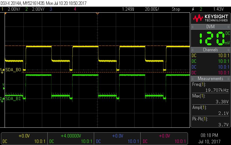
    We have ordered some samples of TCA9802  and attached is the waveform for the communication for the below mentioned scenario, we are able get the data displayed on the system but we want to include more slave before we put the buffer IC.

    Master-->30 Slaves-->(BI) TCA9802 (BO)-->30 Slaves. Each slaves has 4.7k pull up.

    SDA_BI = Data Input to TCA9802

    SDA_BO= Data output from TCA9802

    Can you please help us to improve the communication..

    Thanks

    Krunal Shah

  • Hello Krunal,

    Do you have pull up resistors installed on the B side?  Do you have a schematic?  You can't put pull ups on the B side of the TCA980x devices.  It has an integrated constant current source and it will adversely affect interpreting a low correctly. 

    -Francis Houde