This thread has been locked.

If you have a related question, please click the "Ask a related question" button in the top right corner. The newly created question will be automatically linked to this question.

PCA9545A: Communication issue

Part Number: PCA9545A

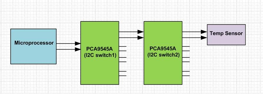
We are using two no of i2C switch in between the Master and slave.(Refer the attached image)  Whether this configuration will work. If it is work, what is the procedure to communicate with slave from master.


I2C Switch1 communication Address: 0x70
I2C Switch2 communication Address: 0x72

  • Hello Auxilian,

    This configuration can work.  You will have to take some precautions about the added series resistance due to series connections and how that will affect VOL/VIL and could cause mismatches.  Why are you trying to do two 4 channel muxes in series.  You could do one 8 channel mux.  Can you explain what you are trying to do and why?  Are you trying to distribute capacitive loading or do using the mux to poll devices that have the same I2C address? 

    The basic procedure to connect to the slave would be to communicate to the I2C switch 1 (address 0x70) and tell it to connect to channel 0 (assuming channel 0 is top bus) by setting control register then send command to I2C switch 2 (address 0x72) to connect its channel 0 to the slave setting its control register. 

    -Francis Houde

  • The two I2C switches available in two different boards in a system. The two boards are originally designed for some other systems.
    Now in the current system, requirement is there to use both the boards and to be inter connected using I2C communication.

    Sequence used to open channel 1 in Switch 1
    Start 0x70(write) 0x01(channel number) Stop
    Device communicated successfully and channel 1 connected


    Sequence used to open channel 1 in switch 2
    Start 0x72(write) 0x01(channel number) Stop
    Now, acknowledgement not received from Switch 2

    Kindly suggest a correct sequence if the current sequence is not correct...

    - James A
  • Hello Auxilian,

    I think you may be a bit confused.  If you want to activate channel 1, then see the table:

    This means you send a hex of 0x02, not 0x01.

    Otherwise the sequence seems correct.

    -Francis Houde

  • Channel 1 what we mentioned is channel 0 in the picture you enclosed... So, for selecting channel 0 we should send hex 0x01 right. We are sending 0x01 only for selecting our required channel (channel 0 - where our i2c device connected)... But with this sequence also acknowledgement not received from Switch 2...