This thread has been locked.

If you have a related question, please click the "Ask a related question" button in the top right corner. The newly created question will be automatically linked to this question.

TCA8418: TCA8418 KEY issue

Part Number: TCA8418

Hi team,

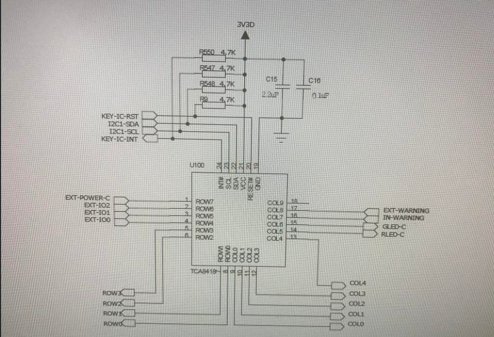
The customer is using TCA8418. The schematic and their code is in the attachment. Please check the attachment.

1. Their design is as below:

(1). COL0-COL4 and ROW0-ROW3 combined to a 4*5 KEYPAD;

(2).  ROW4-ROW6 and COL7-COL8 are GPI. 
(3). ROW7,COL5 and COL6 are GPO. COL9 is not used.
2. Their software design:
(1). Initialize the configuration(void TCA8418_init(void)).
(2). Read the key event and clear the TCA8418 associated flag(void hand_tca8418_event(void). The void hand_tca8418_event(void) function
is called in the MCU  external interrupt function.
3. Their issue:
Q1: When ROW4 is high level and then jump to the low level, the INT pin is pull down to the low level and the INT pin remains low level, it cannot be 
jumped to the high level. Then  TCA8418 does not work and can not generate a normal interrupt signal to inform the MCU. 
The code middleware did not receive the key message.  The customer's requirement is ROW4 pin is Initialized the low level, then if it be detected
the low level, then set it the high level, after followed by loop. What is the reason?
Q2: When the INT pin is pull downed to the low level, read all registers, The INT_STAT and GPIO_INT_STAT1 register values are not 0.
Then clear the INT_STAT and GPIO_INT_STAT1 register values, then the INT pin is pulled up the high level. Then TCA8418 can work fine.
Why  are INT_STAT and GPIO_INT_STAT1 register values not 0 when the INT pin is pull downed to the low level?

Best Wishes,
Mickey Zhang
Asia Customer Support Center
Texas Instruments

1452.code.txt
void iic_delay(void)
{
	unsigend char delaytime = 125;
	while(delaytime--);
}

void TCA8418_reset(void)
{
GPIO_ResetBits(GPIOC,GPIO_Pin_10);	//Pull down reset pin
iic_delay( );
iic_delay( );
iic_delay( );
iic_delay( );
GPIO_SetBits(GPIOC,GPIO_Pin_10);	//Pull up reset pin
}

sendbyteto_TCA8418(xxx,xx);//write to the xx data to the xxx register
readbytefrom_TCA8418(xxx);//read the xxx register value

void TCA8418_init(void)
{
TCA8418_reset()��
iic_delay( );
iic_delay( );
iic_delay( );
iic_delay( ); 
sendbyteto_TCA8418(KP_GPIO1,0x0F);	//write 0x0F to the KP_GPIO1 register
iic_delay( );
sendbyteto_TCA8418(KP_GPIO2,0x1F);
iic_delay( );

sendbyteto_TCA8418(GPIO_DIR1,0x80);
iic_delay( );
sendbyteto_TCA8418(GPIO_DIR2,0x60);
iic_delay( );

sendbyteto_TCA8418(GPIO_INT_EN1,0x70);
iic_delay( );
sendbyteto_TCA8418(GPIO_INT_EN2,0x80);
iic_delay( );
sendbyteto_TCA8418(GPIO_INT_EN3,0x01);
iic_delay( );

sendbyteto_TCA8418(GPIO_DAT_OUT1,0x00);
iic_delay( );
sendbyteto_TCA8418(GPIO_DAT_OUT2,0x00);
iic_delay( );
sendbyteto_TCA8418(GPIO_DAT_OUT3,0x00);
iic_delay( );

sendbyteto_TCA8418(CFG,0x53);//CFG = 0x01
iic_delay( );

}

void hand_tca8418_event(void)
{
	unsigned char int_stat = 0x00;
	unsigned char key_lck_ec = 0x00;
	unsigned char key_event_a = 0x00;
	unsigned char temp = 0x00;
	unsigned char temp_cycle = 0x00;
	int_stat = readbytefrom_TCA8418(INT_STAT);	//read the INT_STAT register value
	if(0x01 == int_stat)
	{
		key_lck_ec =readbytefrom_TCA8418(KEY_LCK_EC);
		temp = key_lck_ec &0x0f;
		if(0x01 == temp)
		{
			key_event_a = readbytefrom_TCA8418(KEY_EVENT_A);
			MSG_DRV_SEND(MOD_KEY_ID,key_event_a);	//Send the key events and parameters to middleware
		}
		else
		{
			if(temp >10)
			temp = 10;
			for(temp_cycle = 0;temp_cycle <temp;temp_cycle++)
			{
				readbytefrom_TCA8418(KEY_EVENT_A);
			}
		}
	}
	else if(0x02 == int_stat)
	{
		temp = readbytefrom_TCA8418(GPIO_INT_STAT1);
		if(0x10 == temp)
		{
			temp = readbytefrom_TCA8418(GPIO_INT_LVL1);
			if(0x10 == temp)
			{
				MSG_DRV_SEND(MOD_KEY_ID,0x65);
				set_low_extio0_int( );


			}
			else
			{

				MSG_DRV_SEND(MOD_KEY_ID,0x65|0x80);
				set_high_extio0_int();

			}


		}
		readbytefrom_TCA8418(GPIO_DAT_STAT1);
		readbytefrom_TCA8418(GPIO_DAT_STAT1);

		readbytefrom_TCA8418(GPIO_DAT_STAT2);
		readbytefrom_TCA8418(GPIO_DAT_STAT2);

		readbytefrom_TCA8418(GPIO_DAT_STAT3);
		readbytefrom_TCA8418(GPIO_DAT_STAT3);


	}
	else
	{


	}
	sendbyteto_TCA8418(INT_STAT,0x1F);

}

unsigned char ext_status = 0x00;

void set_high_extio0_int(void)
{
ext_status |= 0x10;
sendbyteto_TCA8418(GPIO_INT_LVL1,ext_status);


}


void set_low_extio0_int(void)
{
ext_status &= 0xef;
sendbyteto_TCA8418(GPIO_INT_LVL1,ext_status);


}


  • Hello Mickey,

    I haven't had enough time to go through you question and code. I will get a reply to you by tomorrow.  Sorry for the delay.

    -Francis Houde

  • Hi fhoude,

    OK. I will wait for your reply.
  • Hi fhoude,

    Do you have any update? The customer is waiting for my reply.

  • Hello Mickey,

    Q1:  I don't think they are writing 1 to the K_INT bit in INT_STAT register to clear the INT pin.

    Q2:  I am a bit confused about the question.  It sound like the part is operating as it should  When the INT pin goes LOW that means something has happened to changed the state of a bit (generates interrupt) and an INT status flag is changed from 0 to 1.  If you clear INT_STAT bit then it will release the INT pin and it will go to a HIGH state.

    Are they seeing an interrupt they didn't expect????  If so, what and can they send the register settings so I confirm they have set it up properly?

    -Francis Houde

  • hello Mickey && Houde:
    this issue is mine. such is the code .
    void iic_delay(void)
    {
    unsigend char delaytime = 125;
    while(delaytime--);
    }

    void TCA8418_reset(void)
    {
    GPIO_ResetBits(GPIOC,GPIO_Pin_10); //拉低reset引脚
    iic_delay( );
    iic_delay( );
    iic_delay( );
    iic_delay( );
    GPIO_SetBits(GPIOC,GPIO_Pin_10); //拉高reset引脚
    }

    sendbyteto_TCA8418(xxx,xx);//向xxx寄存器中写入xx数据
    readbytefrom_TCA8418(xxx);//读取xxx寄存器的值


    void TCA8418_init(void)
    {
    TCA8418_reset();
    iic_delay( );
    iic_delay( );
    iic_delay( );
    iic_delay( );
    sendbyteto_TCA8418(KP_GPIO1,0x0F); //向KP_GPIO1寄存器写入0x0F,
    iic_delay( );
    sendbyteto_TCA8418(KP_GPIO2,0x1F);
    iic_delay( );

    sendbyteto_TCA8418(GPIO_DIR1,0x80);
    iic_delay( );
    sendbyteto_TCA8418(GPIO_DIR2,0x60);
    iic_delay( );

    sendbyteto_TCA8418(GPIO_INT_EN1,0x70);
    iic_delay( );
    sendbyteto_TCA8418(GPIO_INT_EN2,0x80);
    iic_delay( );
    sendbyteto_TCA8418(GPIO_INT_EN3,0x01);
    iic_delay( );

    sendbyteto_TCA8418(GPIO_DAT_OUT1,0x00);
    iic_delay( );
    sendbyteto_TCA8418(GPIO_DAT_OUT2,0x00);
    iic_delay( );
    sendbyteto_TCA8418(GPIO_DAT_OUT3,0x00);
    iic_delay( );

    sendbyteto_TCA8418(CFG,0x53);//CFG = 0x01
    iic_delay( );

    }

    void hand_tca8418_event(void)
    {
    unsigned char int_stat = 0x00;
    unsigned char key_lck_ec = 0x00;
    unsigned char key_event_a = 0x00;
    unsigned char temp = 0x00;
    unsigned char temp_cycle = 0x00;
    int_stat = readbytefrom_TCA8418(INT_STAT); //读取INT_STAT寄存器的值
    if(0x01 == int_stat)
    {
    key_lck_ec =readbytefrom_TCA8418(KEY_LCK_EC);
    temp = key_lck_ec &0x0f;
    if(0x01 == temp)
    {
    key_event_a = readbytefrom_TCA8418(KEY_EVENT_A);
    MSG_DRV_SEND(MOD_KEY_ID,key_event_a); //向中间件发送按键事件与参数
    }
    else
    {
    if(temp >10)
    temp = 10;
    for(temp_cycle = 0;temp_cycle <temp;temp_cycle++)
    {
    readbytefrom_TCA8418(KEY_EVENT_A);
    }
    }
    }
    else if(0x02 == int_stat)
    {
    temp = readbytefrom_TCA8418(GPIO_INT_STAT1);
    if(0x10 == temp)
    {
    temp = readbytefrom_TCA8418(GPIO_INT_LVL1);
    if(0x10 == temp)
    {
    MSG_DRV_SEND(MOD_KEY_ID,0x65);
    set_low_extio0_int( );


    }
    else
    {

    MSG_DRV_SEND(MOD_KEY_ID,0x65|0x80);
    set_high_extio0_int();

    }


    }
    readbytefrom_TCA8418(GPIO_DAT_STAT1);
    readbytefrom_TCA8418(GPIO_DAT_STAT1);

    readbytefrom_TCA8418(GPIO_DAT_STAT2);
    readbytefrom_TCA8418(GPIO_DAT_STAT2);

    readbytefrom_TCA8418(GPIO_DAT_STAT3);
    readbytefrom_TCA8418(GPIO_DAT_STAT3);


    }
    else
    {


    }
    sendbyteto_TCA8418(INT_STAT,0x1F);

    }

    unsigned char ext_status = 0x00;

    void set_high_extio0_int(void)
    {
    ext_status |= 0x10;
    sendbyteto_TCA8418(GPIO_INT_LVL1,ext_status);


    }


    void set_low_extio0_int(void)
    {
    ext_status &= 0xef;
    sendbyteto_TCA8418(GPIO_INT_LVL1,ext_status);


    }

    i had done some tests ,and got the conclusion.not everytime INT_STAT is 0x00 after iic send 0x1f correctly.
    why?
  • Hello user5053238,

    What microcontroller are you using?  If you are using TI devices than it might be best to have them support your code debug.  I am here to support your hardware debug but without seeing the signals going into the device it is difficult to know what is actually happening to the device. 

    -Francis Houde

  • hello Houde
    microcontroller is stm32f103vgt6. i had done some tests ,and got the conclusion.not everytime INT_STAT is 0x00 after iic send 0x1f correctly.
    why?
  • hello Houde
    please do me the favor to find out the cause of this issue . i am waiting for your reply and solution ,and my team is also.
  • Hello user5053238,

    It sounds like you are saying that sometimes after you have send 0x1F to INT_STAT(0x02) and then you go to read INT_STAT you sometime have something other than 0x00.  

    After looking at your code it seems to me that you are enabling GPIO_INT_EN2 and GPIO_INT_EN3 bits but you never read them or clear them. 

    It appears you are only reading GPIO_INT_STAT1, not STAT2 and STAT3. 

    You need to read GPIO_INT_STAT2 and GPIO_INT_STAT3 and clear (write FF to each register, 0x12 and 0x13) them, assuming their was an event that triggers that INT. 

    -Francis Houde

  • hello Houde
    i have changed my code as your suggestions to do the test .but your suggestions are failed to my issue,i think and the test result seems to.
    the procedure of the test is that after power on the hardwere , the mcu and peripheral finish the initialization, l only pull down the pin row4 to the low level,then pull up pin row4 to the high level, cycle as this. the INT pin will be pulled down to the low level and is low level all the time , can not be pulled up to high level,(the nomal is that INT pin is a negative plus. ).then ,i read all the registers.INT_STAT register is 0x02.in the code ,i have cleared the INT_STAT register.
  • Hello user5053238,

    What you are hex values are you reading from INT_STAT (register address 0x02), GPIO_INT_STAT1 (register address 0x11), GPIO_INT_STAT2 (register address 0x12), GPIO_INT_STAT3 (register address 0x13) when this happens? 

    The INT pin is normally high until an interrupt event happens then it is pulled low.  It stays low until you release it by writing a 1 to the bit that triggered that interrupt event in one of the four registers (INT_STAT, GPIO_INT_STAT1, GPIO_INT_STAT2, GPIO_INT_STAT3). 

    Do you have a schematic so I can verify that the device is connected properly. 

    Do you have oscilloscope/logic analyzer waveforms off all these events.  Do you have a way of recording your I2C transactions for your entire process from programming to initiating the interrupt event?

    -Francis Houde

  • hello Houde
    when this happened, the hex value of each of these four registers is such as , INT_STAT (register address 0x02) is 0x02,GPIO_INT_STAT1 (register address 0x11) is 0x10,GPIO_INT_STAT2 (register address 0x12) is 0x00, GPIO_INT_STAT3 (register address 0x13) is 0x00.


    in the schematic ,row4 connects to a pad of array pads and a diode(positive connects to GND,negative connects to row4 ).the pad will be pulled down to low level when a earphone connect to the array pads, and is float when the earphone disconnect to the array pads.

    do you doubt the I2C transactions?

    thank you for your support.
  • Hello user5053238,

    It is always a good practice to verify the I2C transactions with a oscilloscope to see if you have integrity issues or to confirm a driver is doing what  you expected.  Let me look at the register settings and I will get back if I see anything.  If you can, send me a schematic.  I can receive it off line if that is a problem.  Let me know.  You can click on my account name "fhoude" and click the connect button. 

    Then send me your email or contact information and I can send you my email address.

    -Francis Houde

  • Hello user5053238,
    Are you writing 0xFF to both INT_STAT and GPIO_INT_STAT_1? If so that should clear it and release the INT pin.
    -Francis Houde