This thread has been locked.

If you have a related question, please click the "Ask a related question" button in the top right corner. The newly created question will be automatically linked to this question.

PCA9546A: Asking for the PCA9546A I2C switch control

Part Number: PCA9546A

Hi Team,
Customer uses PCA9546A and met some issues.

Could you help for the questions:
1. If the customer use I2C read, then I2C cannot write successfully. Please provide your comment for this behavior is expected or not?
2. how to know the internal Channel status( open or connect)?


Here two experiment that customer test.
1. write fail case:
step 1: set low on reset pin to reset chip.
step 2 :control Channel 1~4 sequencing.( the master will use I2C to read channel status, if the channel is not connect, customer will use I2C write to set channel to connect.) However, the I2C write is fail.
step 3 : customer use I2C write to write 0 value to turn off all channel. However, it is fail.


2. write success case

step 1: set low on reset pin to reset chip.
step 2 :control Channel 1~4 sequencing.( the master will not use I2C to read channel status. The I2C write is successful.
step 3 : customer use I2C write to write 0 value to turn off all channel. I2C wite is successful. But customer would like to know how to make sure the channel turn off or not.

Thanks,
SHH

  • Hello SHH,
    I am not sure I understand the question.
    1. They should be able to do a write after a read. Please provide I2C waveforms of commands send and in sequence.
    2. If they do a read and look at B3, B2, B1, and B0 bits then they can decode what channels are selected. 1 is ON and 0 is OFF

    Experiment 1
    I don't understand the first step. Why would you hold it in reset???? Do they release it before going to set 2?
    Step 2: Show me waveforms of failed write. I hope they are making sure to generate a stop condition to initiate the channel selection. Seeing the waveforms will let me confirm that.
    Step 3: Show me waveforms please.

    Experiment 2
    They should just be able to just do a read to confirm channels are turned off.

    -Francis Houde
  • Hi Francis,

    We captured the write fail and write/read normal cases.
    For the writes, we can observe the spike at the rising edge both SDA and SCL.
    Cusotmer need to reset PCA9546 to recove the fail situation.

    The write fail is the NACK. Customer need to reset PCA9546A and then can get the ack.

    It is weird behavior. Because the design will reset the PCA9546A at the power up, customer need to reset the PCA9546A again if customer would like to read/write the I2C.
    Could you provide your comment for this NACK issues?

    Here are the waveforms.

    1. write fail case.

    2. write normal case

    3, read normal case


    Thanks,
    SHH

  • Hi team,
    Could you help? Why reset can fix the reset PCA9546 for read//write issues?


    Thanks,
    SHH

  • Hello SHH,
    I am not sure why this is happening. I would like to see if this is a stuck bus and if they can recover from it by generating extra clocks after the read then generate a stop condition before doing the next write. The number of clocks is from 1 to 9 max. I would start with 1 clock then do the stop condition then adjust the number of clocks sequentially until they reach nine clocks.

    Is this problem repeatable and consistent? If so, can they send me the sequence of read and writes that gets the part into what seems to be a stuck bus state? They have a Tek scope with an I2C decoder like I do so I know they can record the sequence. If they send me that I can try and reproduce the problem here.

    I would have them first try doing the steps to recover the bus. If that works, then we need to figure out why it is happening. I will check the sequence and it that doesn't cause it for me here then I can look for more analog reasons for why the bus gets stuck.
    -Francis Houde
  • Hi Francis,

    The problem is repeatable and consistent.

    As you can see, the slave device do not sen ack at the  9 clock. it happen each time after power up the device. (the PCA9546A will be reset each time after power up.)

    Is this enough info. for you?

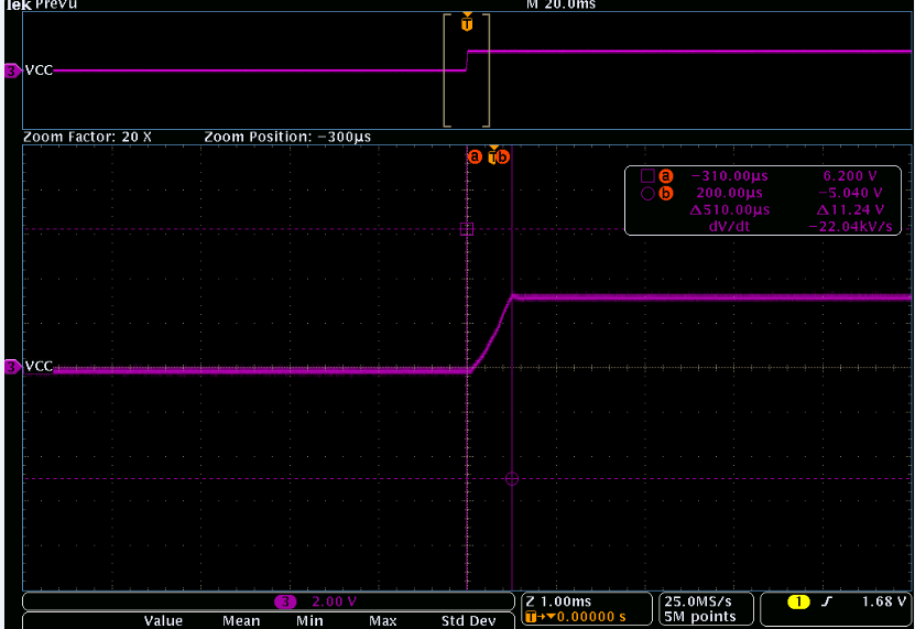
    add the VCC power up timing waveform for reference.The VCC rising is very quick.

    Thanks,

    SHH

  • Hello SHH,
    I understand the problem.
    1)I am trying to find out if they can fix it by clocking the device, which would determine if this is a stuck bus.
    2)If it is repeatable with just the correct sequence of I2C commands then I can try that here and verify from my test setup. If I don't get it to fail with the same commands and sequence then we will have to look at the signal integrity.

    I really need them to verify that it is a stuck bus by the customer doing what I prescribed previously.
    -Francis Houde
  • Hi Francis,

    Could you provide the waveform for the description or datasheet waveform? I am not so clear for this revover waveform looks like.

    "I would like to see if this is a stuck bus and if they can recover from it by generating extra clocks after the read then generate a stop condition before doing the next write. The number of clocks is from 1 to 9 max. I would start with 1 clock then do the stop condition then adjust the number of clocks sequentially until they reach nine clocks. "


    Thanks,
    SHH
  • Hello SHH,

    Here is an example of what I mean.  Yellow=SDA, Blue= SCL. 

    Your customer should know how to do this if they are program I2C devices. 

    -Francis Houde

  • Hi Francis,

    Could you help confirm that customer need to reset the PCA9646 for the disconnection issue?

    conditions:

    1. PCA9546 slave address is E0/E1.
    2. CH1 pin15: I2C Master SDA
    3. CH2 pin14 : I2C Master SCL
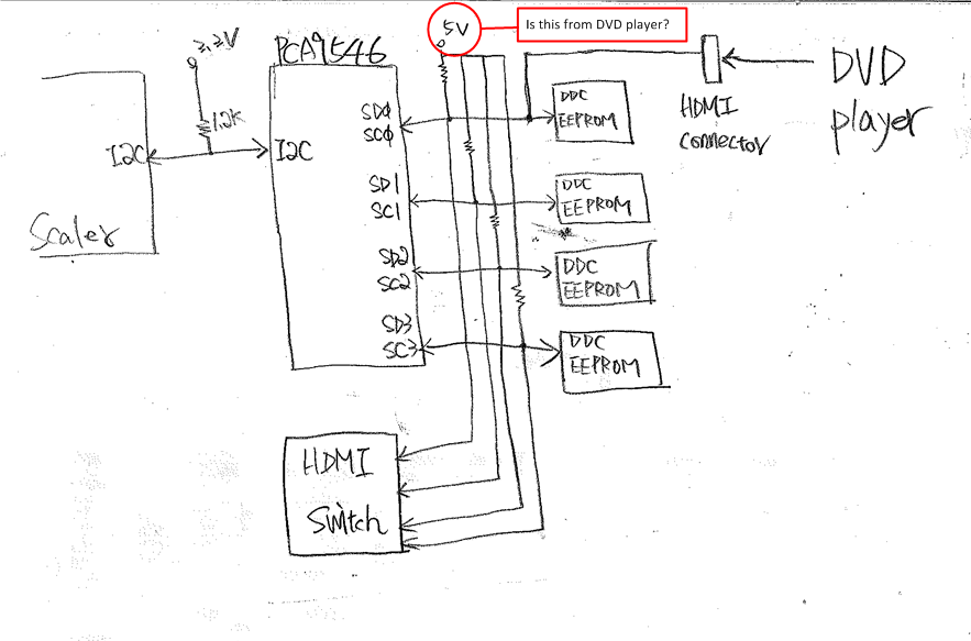
    4. U430 CH0 pin4/5: connect to external DVD's DDC I2C. The DVD's power may turn off, but the PCA9546 still has the power and 3.3_Normal still works. DVD power is different than the PCA9546 system's power


    Issues description
    1. the customer turned off the external DVD power first, then set enable (E0 01) to ebale CHo. customer found the I2C pull high voltage 3.3V dropped to 1.6V.
    2. The I2C pull high voltage will not go high again if customer set enable (E0 00) to CH0. The I2C sill kept at 1.6V. it is weird. customer expect the voltage can be back to 3.3V. 
    3. Customer found that they need to reset PCA9546, the I2C can be recover to 3.3V. Cusotmer would like to know whether the PCA9546 need to be reset to disconnect all the channel in practical. Set (E0 00) doest not work for disconnection for all situation, right?

    PCA9546.tif


    Thanks,
    SHH

  • Hello SHH,

    I have a couple of questions.  In the diagram you attached.  Does the 5V come from the DVD?  What are the pull up resistor values on the SD0/SC0????.

    If the 5V supply is pulled to gound that you could have a resistor divider when the switch is turned on.  Can you clarify exactly on what pins you are seeing the 1.6V???

    -Francis Houde

  • Hi Francis,

    the 5V is from the system, not from the external DVD. pull high resistor is 4.7kohm.
    customer measure 1.6V on pin14/15. Pin 14/15 is 1.6V that is due to the DVD player turn off the power.
    Cusotmer switch to SD0/SD1 and master(pin14/15) disable SD0/SD1, the pin14/15 is still 1.6V.
    The pin14/15 will be recover to 3.3V once customer reset PCA9546.


    Thanks,
    SHH
  • Hello SHH,
    Are they sure the communication to the PCA9546A is getting through? If something from the SD0/SC0 is pulling the SCL/SDA nets low (~1.6V)and the pass FET is ON, then the communications to the part is probably corrupted. Please provide waveforms of the command to disconnect SD0/SC0. My guess is that the command is not being done and you probably see a NACK. Resetting the part works because it's default setting is that all the switches are OFF state at startup.

    We need to know how the connection to the DVD player is affecting the SD0/SC0 lines. If the supply is off and pulled low, then this could cause something like this. You need to check the circuit.
    -Francis Houde