This thread has been locked.

If you have a related question, please click the "Ask a related question" button in the top right corner. The newly created question will be automatically linked to this question.

TCA6424A: IO Expander Power Dissipation

Part Number: TCA6424A

Hi,

In our project, we are going to use this TCA6424ARGJR IO expander part. We need some clarification for the below mentioned points.

1. What is the maximum power dissipated by this part?

2. What is the maximum junction temperature for this part?

3. We are going to use all the IO pins in which each pins sinks a current of about 10mA. Is the part suitable for this kind of applications?

Thanks & Regards,

Shahul

  • Hello Shahul,
    What are you using for a load? an LED? If so, are they all the same Vf? What is the Vcci and Vccp?
    -Francis Houde
  • Hi Francis Houde,

    We are using LED as an load. The vf of each LED is 2.2V.

    VCCI = 3.3V

    VCCP= 3.3V

    Regards,

    Shahul

  • Hello Shahul,

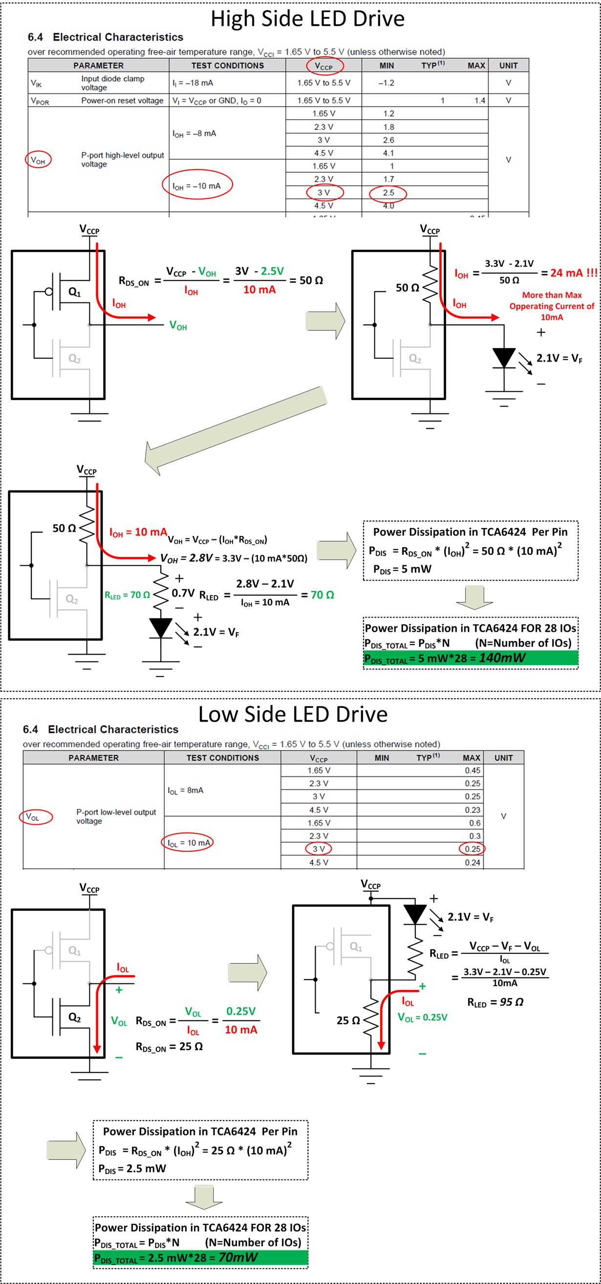
    1) The maximum power dissipated in the part is the power dissipation due to IOs and the ICC. 

    You will need to add some resistance in series with the diode or you will you could damage the part and it will help with power dissipation within the part.  The max I_OH (High-level output current) is 10mA max.    I have drawn a diagram explaining the problem and how to fix it.  See below:

    There are some other added benefits of putting the series resistor, 1) Less of the power dissipation is in the part 2)  The resistance of the FET varies greatly over temps, Vcc, and process, but the resistance of the Rled does not.  That will mean a more consistent current through the LED which means consistent brightness. 

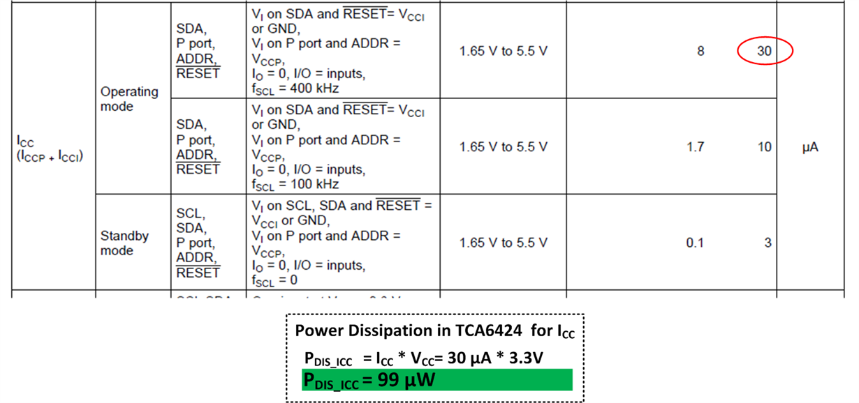
    The power dissipation due to ICC (=ICCP+ICCI) is generally speaking very low compared to this application.  Here is how to calculate it worst case assuming Vcc and Vcci are the same voltage.

    2) As an general approximation use the Max Operating free-air temp as the max junction temp.  We do not guarantee it this way, but is a good way to approximate it. 

    3)  See 1) for answers

    Let me know if you have any more questions.

    -Francis Houde

  • Hello Francis,

    The device is capable of sinking 25mA through each of the I/O.  lf all 24 I/Os need to sink 10mA - then the GND pin should carry 240mA current - which exceeds the absolute maximum rating.

    Is there a recommended maximum continuous current definition for GND pin of this device?

    Thanks

    Sriram SR

  • Hello Sriram,
    You should never exceed the absolute Maximum rating. I recommend to always derating that too for a factor of safety. Also, keep in mind that depending on how you are driving the LED, high side vs low side, the current can be more distributed. The Abs Max Rating for "Continous current" through GND is 200mA, and 160mA for VCCP.
    -Francis Houde