This thread has been locked.

If you have a related question, please click the "Ask a related question" button in the top right corner. The newly created question will be automatically linked to this question.

TCA9617A: The placement of series resistor at BUS B

Part Number: TCA9617A
Other Parts Discussed in Thread: TCA9617B

Hi Team,

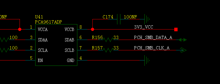
   My customer has a question about the placement of series resistor on TCA9617A design.

   As below figure shown,could you help check the series resistor should place before the pull-up resistor or after the resistor and why? 

Best Regards,

Nick Dai

  • To help explain this, I have decided to show you simulation data. Note that the switch turns on @ 1MHz at a 50% duty cycle.

    R1 and R4 are you series resistor you are asking about.

    R2 and R5 are the pull up resistors. I have chose these values to be 1k to show you a worse case scenario.

    R3 and R6 are the on resistance when the slave/master pulls down (FET Rdon).

    I have chosen an arbitrary bus capacitance.

    ----------------------------------------------------------------------------------------------------------------------------------------------------------------------------------------------------------------

    Lets first take a look at what happens when side A pulls low:

    Note that side B has a buffered voltage offset of 0.5V.....

    As you can see from the graph, when side A pulls low, the voltage to the slave/master on side B is correlated to the resistors in series. What we see is if the resistor comes before the pull ups, a larger voltage offset is observed. However if the series resistor comes after the pull up, the same static voltage offset is observed.

    The voltage we see in the case of before the pull up, lets call it Vx, is a function of: Vx= Voltage offset + [R1/(R1+R2)]xVcc

    From the equation above, we can see if we raise R2 then Vx will decrease. Though R2 is determined by the bus capacitance and expected Vol and I(ol). You will need a lower value for faster speeds.

    One last thing you can note about this graph is if the resistor is placed after, the rise time is affected. This is because the series resistor adds with the pull up resistor giving us a larger equivalent resistance.

    ----------------------------------------------------------------------------------------------------------------------------------------------------------------------------------------------------------------

    When B side pulls down (no offset):

    note: Vx pin (BEFORE and AFTER) were moved

    From above, we can see that when the transceiver on B side pulls down, if the series resistor comes after, the voltage seen by the TCA9617A is larger than if the series resistor came before. In this case, Vx is a function of: Vx = Vcc x {(R4+R6)/[(R4+R6)+R5]}

    From the function above, with a larger R4, the voltage increase on Vx grows larger. The opposite occurs when R5 is increased however this will affect the pull up time.

    ----------------------------------------------------------------------------------------------------------------------------------------------------------------------------------------------------------------

    From the analysis above, we should place the resistor after the pull up however care should be taken to ensure that when B side pulls low the TCA9617A sees the low. In this case lets call Vx = 0.4V (Vil of B side).

    Solving for R4....

    R4<=[0.4(R6+R5)-Vcc*R6]/(Vcc-0.4)

    Plugging everything in from my previous examples.... R4<=56.95

    So finally lets see what happens when you have a series resistor that is too large?

    For this I have chosen R4 to be 60 ohms which is larger than the 57 I calculated.......

    As you can see from above, because R4 is larger, we see a larger offset. TCA9617A sees 0.4V Vil as a low however what it sees now is 0.412V which is not lower than the required. This results in A side never being pulled low by B side.

    For this reason, make sure the series resistance is not too large!!!!


    Finally, may I ask why you are placing a series resistor on the I2C bus, I typically don't see this and I am curious to know.

    Thanks,

    -Bobby


  • Hello Nick, 

    I would like to add one more suggestion to the customer.  I would recommend that they use the TCA9617B which has Power-Off High Impedance on I2C bus, which the TCA9617A does not. 

    -Francis Houde