This thread has been locked.

If you have a related question, please click the "Ask a related question" button in the top right corner. The newly created question will be automatically linked to this question.

TCA9544A: Problem with channel selection

Part Number: TCA9544A

Hello,

I want to use the TCA9544A to communicate with four light sensors. I want to use it as multiplexer and also as a level shifter to get from a 5V I2C from my Master to a 3.3V level of my slave. But I can't select the channels of the TCA9544A. My Master is an ATmega328P.

At first I just want to select channel 0

I send a start condition with the address 0x70h and a write bit

--> i2c_start(MUX_adr + I2C_WRITE);

afterwards I want to selct channel 0 with 0x04h

--> i2c_write(MUX_channel_adr);

after this i just set a stop condition and want to talk with my light sensor

--> i2c_stop();

I tried to debug a bit and it seems that I can send the start condition, but it gets stucked somewhere in the part where I want to write to the register to select the Channel.


I use a I2C clock frequency with 400kHz do I have to enable the fast Mode somehowe?


Thank you already for your help!

  • Hey again Phillip!

    Your code flow control looks correct and in theory should work. Let's try focusing on the hardware and what the signals tells us.

    Can you provide a picture of your schematic (the TCA9544A) and scope shots of SDA and SCL when you try communicating with our device? Ideally when you try to send the address and R/W bit. This should give us a better idea of what may be going on.

    "I use a I2C clock frequency with 400kHz do I have to enable the fast Mode somehowe?"

    -Nope, the device will handle it with its state machine by looking at SCL.

    Thanks,

    -Bobby

  • Hei Bobby!

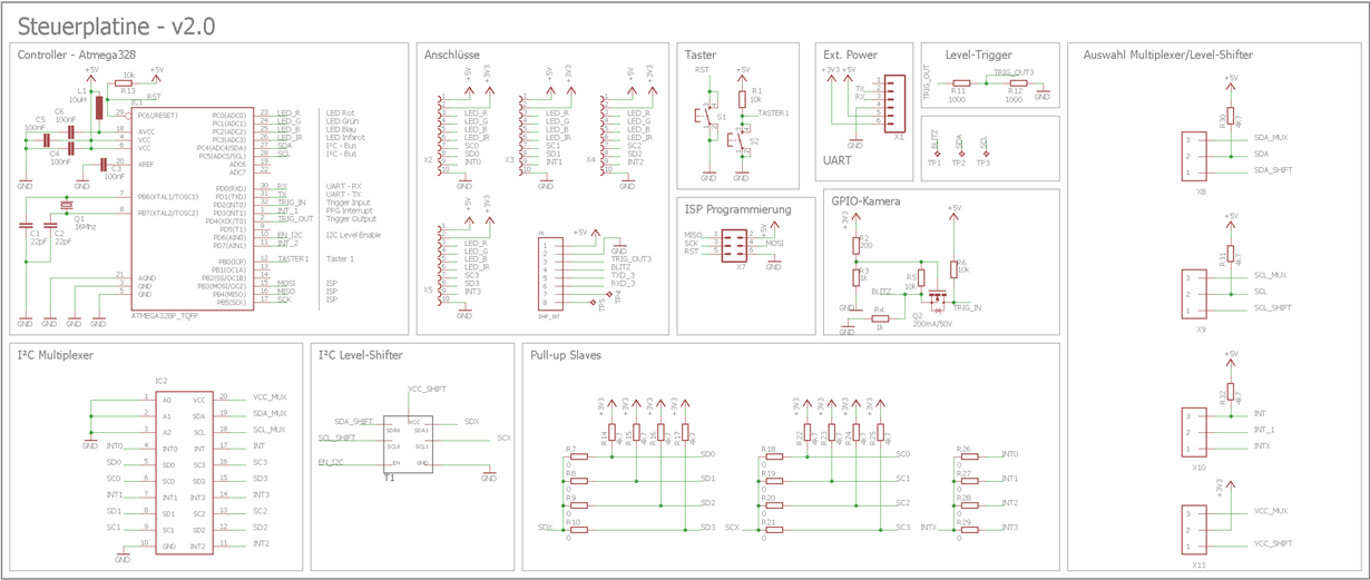
    already thank you for your help. Unfortunatly I have no Osziloscope to make shots of the signal. But I can give you the schematic.

    There are a few jumper on the board to swich between the Multiplexer and a I2C level shifter(that's from an old version and actually I don't want to use ist anymore, because the  TCA9544A should be enough). The 0Ohm resistors at the slave side, are not implemented while I use the Multiplexer and I aslo don't use the Jumper for the interrupts, because I think the pull up resistor should go to 3.3V and not to 5V. But that shouldn't be a problem because I don't use interrups yet.

    Thousend thanks for your help Bobby

    -Philipp

  • Hey Phillip,

    I'm not seeing any issues with your schematic. I assume when you try to communicate you have a short/jumpers to pins 3 and 2 of your headers from SDA/SCL and SDA_MUX/SCL_MUX. The address you are sending looks correct at 0x70h and matches with what you've stated with software.

    I think we need scope shots to get a better picture of whats going on. That way we can verify if the data being sent is correct and also see if we receive an ACK from our device. It could also be possible that cross talk is occurring and affecting the signal integrity of our I2C line. It could also be possible you've swapped the SDA/SCL lines with our device and the mcu. Without an oscope shot, I would just be guessing what could be going wrong.

    In the mean time, you could try doing a continuity check and seeing if the SDA_MUX/SCL_MUX with SDA/SCL of the mcu are indeed connected. I would also double check and see if the GNDs of the multiplexer and mcu are connected. Then go on and check if the lines are indeed seeing the pull up values you should expect. Double check the soldering on the ICs to make sure they are connected to the PCB. INT0-INT3 should also be pulled up so you want to double check that as well.

    Thanks,
    -Bobby
  • Hey Bobby,

    ok i try to organize an osziloscope and will check the other things you mentioned.

    Thanks

    Philipp

  • Hey Bobby,

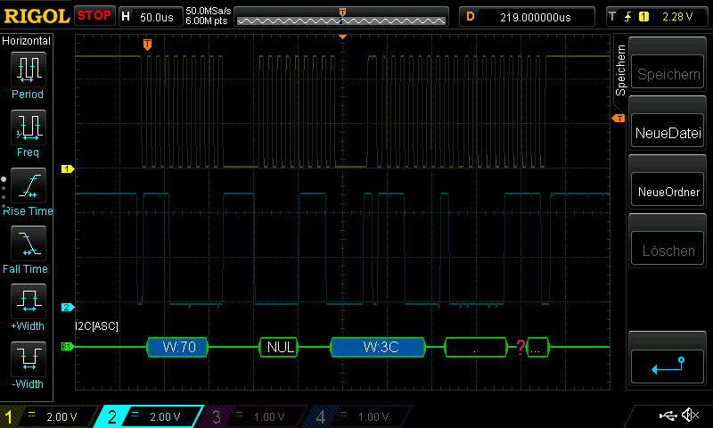
    I tried to find the error on my PCB. It looks like the TCA9544A dosen't activate the Channel. I can communicate with it and when I read it, it returs the right value of the selected channel. I organized an Oszi and tried to scope the I2C signlas. 

    The signals from the Controller seem fine for me. But  there is no signal on the other side of the Multiplexer. The voltage level is on 3.3V like they should be.

    Do you have any idea what it could be? Is it possible that the Multiplexer is broken, but then it shouldn't be possible to communicate with it?

    greetings

    Philipp

  • Hey Phillip,

    Thanks for the scope shot. I don't see any major glitches or anything out of the ordinary from the shots. Though the clock signal being held low does seem a bit odd I believe it should still work since you are still getting ACKs.

    If I am reading the o-scope correctly, it looks like you are talking to address 0x70h write for the first transaction. Then you write in the register 0x07h which means you are enabling channel 3 (and only channel 3). Afterwards you resend the address but this time with a read and then read the address which is 0x07h.

    " It looks like the TCA9544A dosen't activate the Channel."
    How are you verifying this? Can you pull channel 3 to GND (either SDA/SCL) and check to see if the main SDA/SCL lines also get pulled to GND?

    Thanks,
    -Bobby
  • Yes I just wanted to enable any channel and read it back, so I can be sure that I have sent the right signal.

    I think that the channel isn't selected, because after I enabled the channel I send a Signal to my sensor. I can scope the right signal out of the controller but I can't scope it after the Multplexer. That's why I'm thinking that the Channel is might not activated.

    I haven't tried to get SCL or SDL on ground yet. But I'll try it

    Thaks for your help Bobby!

    Philipp

  • Hello Philipp,
    You need to generate a STOP condition before the channels are actually actuated. A repeated start or just idle won't actually initiate what is loaded in the register space. The guidelines for the process writing to the registers has this included, see the datasheet.
    -Francis Houde
  • Hello Francis,

    actually I generate a normal Stop condition after I selec the channel. My source code looks like this:

    i2c_start_wait(MUX_adr + I2C_WRITE);

    i2c_write(0x07);

    i2c_rep_start(MUX_adr + I2C_READ); // set device address and read mode

    ret = i2c_readNak(); // read one byte

    i2c_stop();

    after the stop contition I try to communicate with my sensor. I am sure, that my code for this is correct, because it wokes if I don't use the Multiplexer.

    Greetings

    Philipp

  • Hello Philipp,

    You need to get generate a STOP condition right after you write 0x07 to control register.  You see in the waveform you do a repeated start (in circle, you need a stop condition there).  I think that is your problem.  

    Let me know if this fixes your problem or if you have more questions.

    -Francis Houde