Hi,
I am working in P82B715 IC for Long distance I2C communication. I have a doubt.
In datasheet it is mentioned that Voltage logic levels are independent of VCC and also the IC has to sink 30mA.
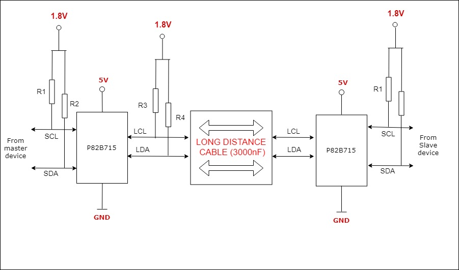
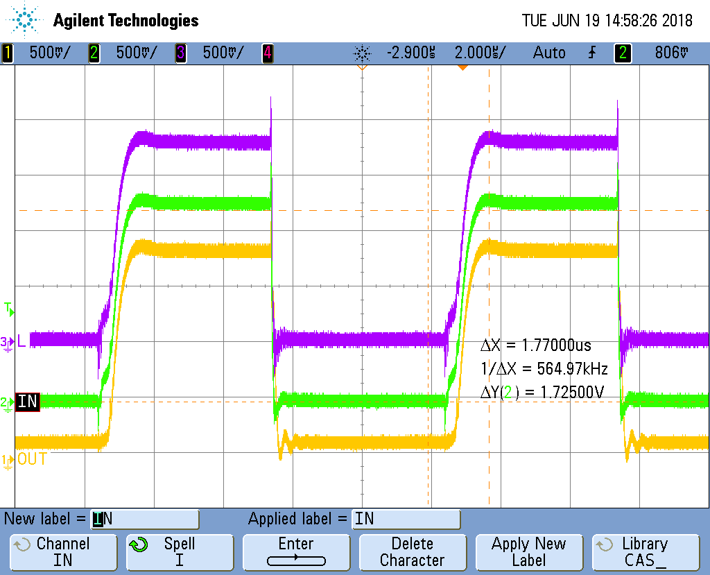
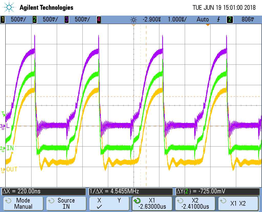
So can I use pull-up voltage of 1.8V for Sx/Lx signals with VCC of 5V and calculate pull-up resitance values to provide sink current value of maaximum 30mA. Also I calculate RC value to provide 1uS rise and fall time.
If I do so, there will be still any problem in sinking current or timings? or else any other problem will arise??
Please explain me whether my ubderstanding is correct or not
Thanks,
Arun