This thread has been locked.

If you have a related question, please click the "Ask a related question" button in the top right corner. The newly created question will be automatically linked to this question.

Problem with SN65HVD230 with BeagleBone

Other Parts Discussed in Thread: SN65HVD230

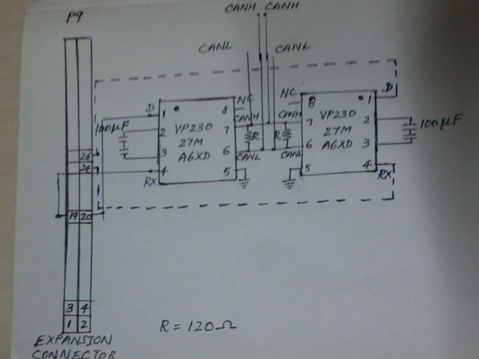
 We  have interfaced SN65HVD230  with Beagle Bone's CAN Port and  the CAN Tx line is staying at High  when we are sendingd data.We are connecting in loopback mode with  one CAN transceiver CANH tied to other transceiver's  CANH and similiarly  for CANL also.  Is there any limitation for SN65HVD230 to work with other TI's microprocessors with CAN support. The datasheeet shows operation with TMS320LF243  and is it limited to this proceesor or this is a generic transceiver ?


Please share your comments.if anybody interfaced this IC with Beagle bone and  got working .

  • Can you please clarify the following pionts of basic CAN debug so we can help you further.  The SN54HVD23x familly whould work fine with Beagle Bone (AM35xx). 

    The TXD pin is controlled by the MCU not the transceiver so I suspect you actually have s/w set up issues with the AM35xx CAN data and the transceiver isn't even getting any.  I'm not sure what you mean by loop back mode, is this a mode on AM35xx like on Stellaris where the data never actually comes out to the bus (transceiver) but is looped back internally on the CAN controller of the uP?

    CANH and CANL should be connected in linear bus fashion from the transcievers, with 120 ohm resistors at each end of the bus since it is a transmissions line and they are needed for CAN to work properly.  Please see app note SLOA101A  for CAN bus basics.  Up through page 8 should get you the basic info to help a lot. 

    If you can send a scope shot with the following it will let us know what is going on with the transceiver.  We need TXD (D), RXD (R), CANH and CANL.  Best is to put CANH and CANL at the same reference point as in recessive (logic 1 or high) they will be the same potential (~2.3V) and when you transmit a dominant (logic 0 or low) they will be seperated and CANH should rise to about 2.8V and CANL should drop to about 1.5V).   This will basically confirm if you are getting correct data out of the uP to the CAN transceiver.   Schematics of you set up would also be helpful.

    Other app notes that may help (hyperlinks hopefully work):

    SLOA101A: Introduction to the Controller Area Network (CAN)
    SLLA270: Controller Area Network Physical Layer Requirements
    SLLA271:  Common Mode Chokes in CAN Networks: Source of Unexpected Transients
    SLLA279A: Critical Spacing of CAN Bus Connections
    SLLA109: A System Evaluation of CAN Transceivers
    SLLA123: Using CAN Arbitration for Electrical Layer Testing
    SLLA298B: Isolated CAN Reference Design
    SLLA107: Live Insertion With Differential Interface Products
    SLLA067B:  Comparing Bus Solutions
    Article: “Signaling rate versus cable length: the CAN-bus timing trade-off” – CAN loop timing and arbitration

    -- Scott

  • Hi Scott ,

            We belong to the software team of Ajish who posted question on this. You can see the schematic of what we have  done in the image below.

             Using CAN utilities , we tested CAN interfaces by sending and receiving data's in loopback mode , which is working fine . Also , we were able to see the signal change in DCAN0_TX pin .

            Then , on connecting the DCAN0_TX(P9- 20th pin) and DCAN0_RX(P9-19th pin) of the beaglebone to tx(D) and rx pin of the CAN transceiver and similarly DCAN1_TX(P9-26th pin) and DCAN0_RX(P9-24th pin) is connected to the tx(D) and rx pin of the other CAN transceiver , thus making loopback as Ajish said, we see only high signal on tx and rx.

    Hope you can help us further with this information.

    Thanks in advance,

    Dhiv.


  • Schematically it seems to have 3 issues. 

    • Pin 8 which is the mode control, Rs should not be floating. Pin 8 floating may mean you are in low power standy mode which would not put data from D pin to the bus and thus no output to R. Please tie Pin 8, Rs to GND.
    • Pin 5 is Vref output pin.  This pin should not be tied to GND, that is a direct short to GND of this output.  Either leave it floating or use a capacitor to GND in the 100pF range.
    • Pin 3 is Vcc.  It should have 3.3V applied not just capacitors to GND (pin 2).
    •   Ideally a scope shot of D, R, CANH and CANL (with both at same reference) will be very helpful to see what is actually happening at the pins of the device in question.  Without basic scope debug there is a lot to guess about but little to offer solid advice.

    Please see look at figure 39, right end CAN node (SN65HVD230) in the datasheet for a basic schematic on how to use the device.

    Then please confirm the following: 

    • Pin 8: Rs is tied to gnd for High Speed Mode.
    • Pin 3: Vcc on pin 3 with respect to pin 2 is 3.3V.
    • Pin 5: is floating or capacitor to GND
    • The output levels of Sitara is set up to 3.3V thresholds of HVD230.  Make sure it isn't an open drain output or the timing input to the transceiver will not work.  There is only a weak pull up to hold the part in recessive (logic H) if TXD floats.  TXD timing will be way to slow in that case.
    • Output level on CANH and CANL.  Please see if they are DC at about 2.3V or actually have transitions.
    • As requested originally, a scope plot showing the signal path of the uP (TXD / D) to the transceiver, then the bus and back out of the receiver (R) to the uP (RXD) will help eliminate a lot of possible issues.

    -- Scott

  • See the correction above. -- Scott

  • Thanks for the reply scott .

    We have connected gnd and vcc to the corresponding pins of transceiver as you said , but left out in the schematic by mistake. We will make all other corrections as you said , and get back to you.

    Regards,

    Dhiv .

  • Thank you so much Scott. We couldn't have done it without your help. After making the changes , now both the interfaces are working fine . Transmission and reception are perfect between DCAN0 and DCAN1.

    Thanks and regards,

    Dhiv :)

  • Thank you Scott  for the review and comments to our post.


    Regards,

    Ajish